


Chapter
Twelve
:
Practical
Modeling
Examples
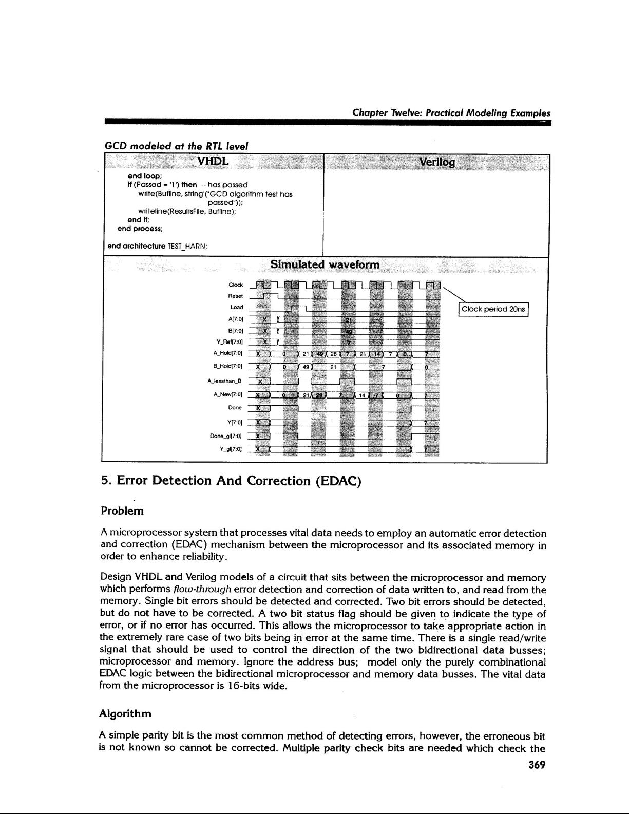
GCD
modeled
at
the
RTL
level
Verilog
•
-
'
VHDL
-
end
loop
;
Passed
=
1
)
then
-
has
passed
write
(
Bufline
,
string
'
'("GCD
algorithm
test
has
passed
"
)
)
;
writeline
(
ResultsFile
,
Bufline
)
;
end
If
;
end
process
;
end
architecture
TEST_HARN
;
Simulated
waveform
-
Clock
period
20
ns
A
[7
B
[
[7
:
0
]
Y
_
Re
f
[
7
:
0
]
X
X
0
21
~
49
~
28
~
~
2
1
j
14
^
~
~
0
~
A
_
Hol
<
j
(
7
;
01
B
_
HokJ
(
7
:
0
]
r
-
i
T
—
-
M
A
_
New
(
7
:
0
]
m
few
Y
[
7
:
0
|
:
H
V
Done
.
glI
7
:
0
]
"
i
V
_
gl
7
:
0
]
5
.
Error
Detection
And
Correction
(
EDAC
)
Problem
A
microprocessor
system
that
processes
vital
data
needs
to
employ
an
automatic
error
detection
and
correction
(
EDAC
)
mechanism
between
the
microprocessor
and
its
associated
memory
in
order
to
enhance
reliability
.
Design
VHDL
and
Verilog
models
of
a
circuit
that
sits
between
the
microprocessor
and
memory
which
performs
flow
-
through
error
detection
and
correction
of
data
written
to
,
and
read
from
the
memory
.
Single
bit
errors
should
be
detected
and
corrected
.
Two
bit
errors
should
be
detected
,
but
do
not
have
to
be
corrected
.
A
two
bit
status
flag
should
be
given
to
indicate
the
type
of
error
,
or
if
no
error
has
occurred
.
This
allows
the
microprocessor
to
take
appropriate
action
in
the
extremely
rare
case
of
two
bits
being
in
error
at
the
same
time
.
There
is
a
single
read
/
write
signal
that
should
be
used
to
control
the
direction
of
the
two
bidirectional
data
busses
;
microprocessor
and
memory
.
Ignore
the
address
bus
;
model
only
the
purely
combinational
EDAC
logic
between
the
bidirectional
microprocessor
and
memory
data
busses
.
The
vital
data
from
the
microprocessor
is
16
-
bits
wide
.
Algorithm
A
simple
parity
bit
is
the
most
common
method
of
detecting
errors
,
however
,
the
erroneous
bit
is
not
known
so
cannot
be
corrected
.
Multiple
parity
check
bits
are
needed
which
check
the
369


评论0