
For Academic Use Only
This material exempt per Department of Commerce license exception TSU
Lab 2: Adding IP to a Hardware
Design Lab
Targeting MicroBlaze™ XUP Spartan™-3E
Adding IP to a Hardware Design Lab: www.xilinx.com/univ 2-3
MicroBlaze Processor [email protected]
Lab 2: Adding IP to a Hardware Design Lab
Introduction
This lab guides you through the process of adding additional IP to an existing processor system by
using Xilinx Platform Studio (XPS). You will learn to add additional IP using the IP Catalog tab.
At the end of the lab, you will create the design netlists and implement the design by using the
ISE™ flow.
Objectives
After completing this lab, you will be able to:
� Add additional IP to a hardware design
� Implement the design by utilizing ISE
Procedure
The purpose of this lab exercise is to extend the hardware design started in Lab 1. Lab 1 included
the MicroBlaze processor, LMB bus and LMB memory, two GPIOs, and MDM. Lab 2 adds
another GPIO to extend the hardware design.
In this lab, you will use the dialog mode of the XPS system and text mode features to add the
following IP to an existing processor system (Figure 2-1):
� OPB GPIO for Push button for I/O purpose
You will also analyze the system.mhs file to understand the various sections of the hardware
specifications of the microprocessor.
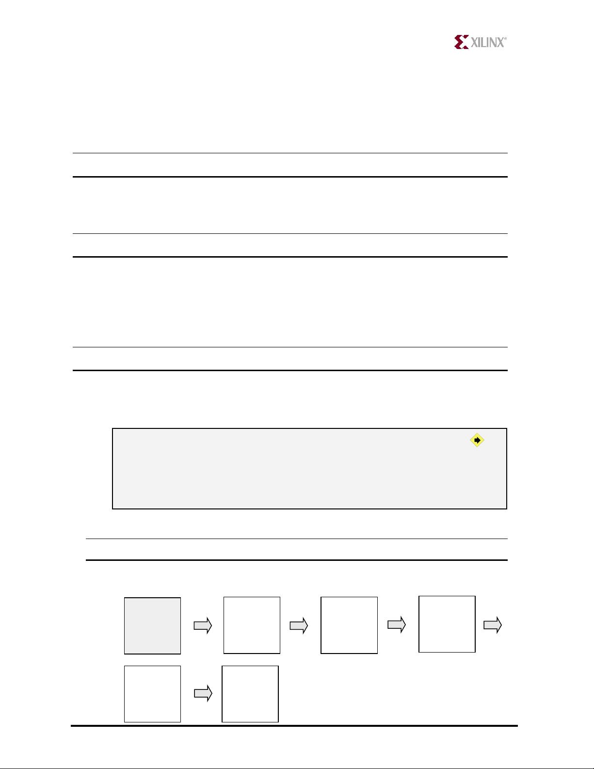
Figure 2-1. Completed Design
This lab comprises five primary steps: You will add IP to the processor system designed in Lab 1,
extend the hardware system, analyze the MHS file, and create a Project Navigator project used to
MicroBlaze
LMB
BRAM
Cntl
r
BRAM
LMB
BRAM
Cntlr
OPB
Bus
PSB
UART
INTC
Timer
GPIO
GPIO
MY IP
LEDs
LCD
MDM
IBA
ICON

Adding IP to a Hardware Design Lab: www.xilinx.com/univ 2-4
MicroBlaze Processor [email protected]
implement the design. You will then add a software application, generate a bitstream, download in
hardware and verify the functionality.
For each procedure within a primary step, there are general instructions (indicated by the
symbol). These general instructions only provide a broad outline for performing the procedure.
Below these general instructions, you will find accompanying step-by-step directions and
illustrated figures that provide more detail for performing the procedure. If you feel confident
about completing a procedure, you can skip the step-by-step directions and move on to the next
general instruction.
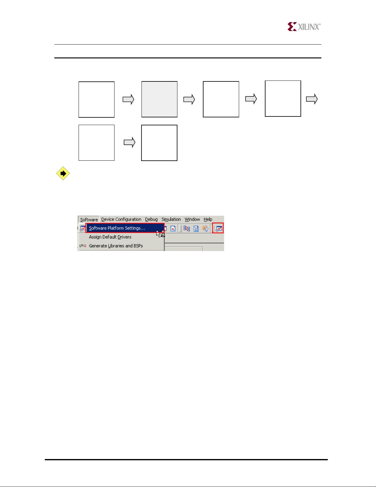
Adding IP to the Processor System Step 1
General Flow for this Lab:
Create a lab2 folder and copy the contents of the lab1 folder into the lab2 folder if
you wish to continue with the design you created in the previous lab. Launch
Xilinx Platform Studio (XPS) and open the project file located in either the
c:\xup\embedded\labs\lab2 (if you want to continue with your created design) or
c:\xup\embedded\completed\lab1.
If you wish to continue using the design that you created in Lab 1, create a lab2mb folder in
the c:\xup\embedded\labs directory and copy the contents from lab1 to lab2
Step 1:
Adding IP to
the Processor
System
Step 2:
Extending the
Hardware
System
Step 3:
Analyzing the
MHS File
Step 4:
Creating a
Project
Navigator
Project
Step 5:
Verify in
Hardware
Adding IP to a Hardware Design Lab: www.xilinx.com/univ 2-5
MicroBlaze Processor [email protected]
Open XPS by selecting Start � Programs � Xilinx Platform Studio 8.1i � Xilinx Platform
Studio
Select File � Open Project and browse to either the c:\xup\embedded\labs\lab2 or
c:\xup\embedded\completed\lab1 folder
Select system.xmp to open the project
Extending the Hardware System Step 2
General Flow for this Lab:
Add the following IP to the processor system using System Assembly View
panel:
o OPB GPIO
XPS provides two methods for adding peripherals to an existing project. You will
use the first method, the System Assembly View panel, to add most of the
additional IP and connect them. The second method is to manually edit MHS file.
Select IP Catalog tab in the left window and click on plus sign next to General Purpose IO
entry to view the available cores under it (Figure 2-2)
Step 1:
Adding IP to
the Processor
System
Step 2:
Extending the
Hardware
System
Step 3:
Analyzing the
MHS File
Step 4:
Creating a
Project
Navigator
Project
Step 5:
Verify in
Hardware
Adding IP to a Hardware Design Lab: www.xilinx.com/univ 2-6
MicroBlaze Processor [email protected]
Figure 2-2. System Assembly View
Select the opb_gpio core (version 3.01.b) in the IP Catalog window and drag it in the System
Assembly View window and drop it under the dcm_0 entry
You cam also add by selecting the core and double-clicking on it.
Change the instance names of the opb_gpio_0 peripheral to Push_Buttons_4Bit, by clicking
once in the name column, by typing the new name for the peripheral followed by pressing
Enter key
At this point, the Peripherals tab should look like the following (Figure 2-3):
!
!