没有合适的资源?快使用搜索试试~ 我知道了~
心电起博器参考设计,心电起博器参考设计
需积分: 5 0 下载量 13 浏览量
2023-09-22
16:52:29
上传
评论
收藏 1.26MB PDF 举报
温馨提示
试读
22页
心电起博器参考设计
资源推荐
资源详情
资源评论
An IMPORTANT NOTICE at the end of this TI reference design addresses authorized use, intellectual property matters and
other important disclaimers and information.
TINA-TI is a trademark of Texas Instruments
WEBENCH is a registered trademark of Texas Instruments
TIDUB75-November 2015 Software Pacemaker Detection Reference Design 1
Copyright © 2015, Texas Instruments Incorporated
Brian Pisani
TI Precision Designs: Verified Design
Software Pacemaker Detection Reference Design
TI Precision Designs Circuit Description
TI Precision Designs are analog solutions created by
TI’s analog experts. Verified Designs offer the theory,
component selection, simulation, complete PCB
schematic & layout, bill of materials, and measured
performance of useful circuits. Circuit modifications
that help to meet alternate design goals are also
discussed.
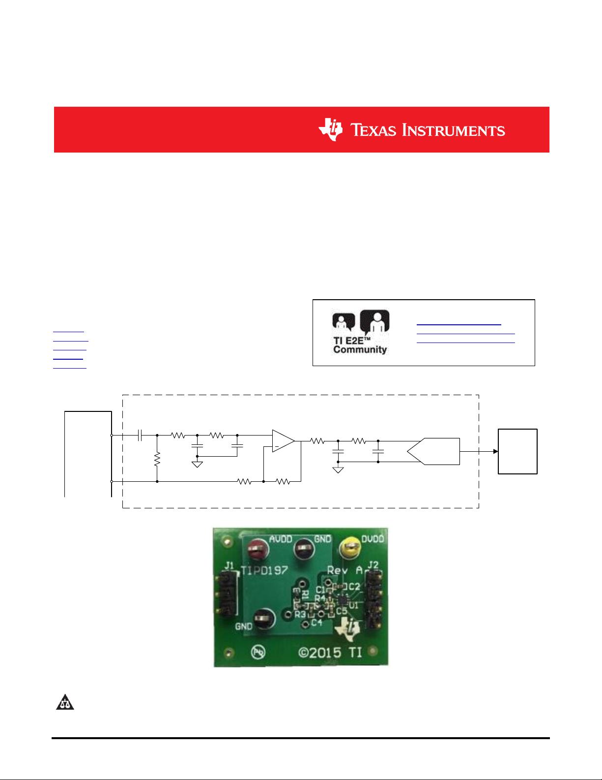
This circuit is designed to condition and digitize an
electrocardiogram signal output from the integrated
PACE_OUT buffer on the ADS129x to detect artifacts
of a pacemaker. This circuit includes an op amp
which serves as a signal conditioner and input driver
for a fast-sampling SAR ADC. The ADC
communicates using an SPI compatible interface.
This document also discusses developing a detection
algorithm and other digital signal processing
considerations.
Design Resources
TIPD197 All Design files
TINA-TI™ SPICE Simulator
ADS7042 Product Folder
OPA320 Product Folder
ADS1298 Product Folder
Ask The Analog Experts
WEBENCH® Design Center
TI Precision Designs Library
ADS7042
+
C
Block
R
Bias
R
s
R
f
R
Anti-alias
R
Anti-alias
R
Anti-alias
R
Anti-alias
C
Anti-alias
C
Anti-alias
C
Anti-alias
C
Anti-alias
DSP/FPGA/
MCU
OPA320
PACE_OUTx
VCAP2
ADS129x
TIPD197
www.ti.com
2 Software Pacemaker Detection Reference Design TIDUB75-November 2015
Copyright © 2015, Texas Instruments Incorporated
1 Design Summary
The design requirements are to resolve pacemaker signals with the following characteristics such that they
can be detected with a strong software pace detection algorithm:
0.5 ms – 2 ms pacemaker signal width
±2 mV – ±250 mV pacemaker signal magnitude
100 μs maximum rise time
This design showcases a topology which has proven to provide a user with the ability to detect the
presence of a pacemaker. The specific values of the gains, target cutoff frequencies, thresholds, etc. are
flexible to allow systems with inherent variations to find a reliable combination.
Figure 1 shows an electrocardiogram signal with a pacemaker present (top) and after being output from a
digital high pass filter showing thresholds used to trigger detection (bottom).
Figure 1: Example pacemaker signal capture using TIPD197 (top) and after detection algorithm (bottom)
-1
0
1
2
3
0.1 0.2 0.3 0.4 0.5 0.6 0.7 0.8 0.9
Voltage
(mV)
Time (s)
-1
0
1
2
3
0.1 0.2 0.3 0.4 0.5 0.6 0.7 0.8 0.9
Voltage
(mV)
Time (s)
www.ti.com
TIDUB75-November 2015 Software Pacemaker Detection Reference Design 3
Copyright © 2015, Texas Instruments Incorporated
2 Theory of Operation
According to AAMI EC11, medical instrumentation must be capable of displaying pacemaker pulses with
amplitudes between 2 and 250 mV, durations between 0.5 and 2 ms, and a rise time of less than 100 μs.
These parameters will be used as the basis for defining the signal that this solution aims to detect. Figure
2 shows a circuit that may be used to detect a pacemaker pulse.
+
DSP/FPGA/
MCU
+
+
Mid-supply
SAR ADC
+
-
ECG
Lead
Differential
Amplifier
Differential to
single-ended
converter
Non-inverting
Gain Stage/
ADC Front
End
AC
Coupling
Anti-aliasing
Anti-aliasing
v
REF
+
Figure 2: Pacemaker detection circuit
The transfer function measured as the output digital code of the ADC is shown in Equation ( 1 ). The
quantity G
total
represents the total gain from all of the amplifier stages.
Ref
2
CodeOutput
v
G
v
N
total
Lea d
( 1 )
2.1 Understanding a Pacemaker Pulse
A pacemaker artifact will appear as a narrow pulse in an ECG waveform. The amplitude at which the
pacemaker signal appears in the ECG signal depends on the lead.
The characteristic of a pacemaker pulse which separates it from other biopotential signals is its fast rise
time and narrow width. In general, these characteristics will be leveraged in detection, but also they
provide constraints on the design. Figure 3 shows and example Lead II ECG waveform with a ventricular
pacer present.
Figure 3: Example ECG signal with pacemaker present
Such a narrow pulse would intuitively suggest a wide bandwidth. In this design, the narrowest pulse
targeted for detection measures 0.5 ms. A bandwidth of 4 kHz is sufficient to resolve the pulse. The
Nyquist inequality dictates that systems must sample more than twice as fast as the bandwidth. In practice
the signals should be well oversampled to produce a better reconstruction.
-2
-1
0
1
2
3
4
0 0.1 0.2 0.3 0.4 0.5 0.6 0.7 0.8 0.9 1
Voltage
(mV)
Time (s)
www.ti.com
4 Software Pacemaker Detection Reference Design TIDUB75-November 2015
Copyright © 2015, Texas Instruments Incorporated
In addition to the constraint created by the speed of the pulse, it also has the potential to be small in
magnitude. The input referred noise must be less than 2 mV if the pulse is to be identified. Ideally it should
be significantly smaller than 2 mV to prevent a false detection. How much margin is needed exactly will
depend largely on the detection algorithm.
2.2 Signal Conditioning
An ECG signal needs to be conditioned to be made ideal for pacemaker detection. The signal may need
gain, electrode offset needs to be removed, and the signal should be biased at the mid-supply voltage of
the ADC to provide the signal with the maximum possible range within the ADC’s conversion range.
2.2.1 ECG Front End
A typical ECG lead is comprised of the difference between potentials at two electrodes. For instance Lead
I is defined as LA – RA. This means the front end of any ECG sensor must be differential. The front end
must also comply with medical regulatory standards which limit the amount of current that can flow in our
out of electronic medical equipment. A differential amplifier with a high impedance input is a natural choice
for ECG front end since it meets both requirements.
Figure 4 shows a differential amplifier as an ECG front end. Gain can be provided by selecting R
f
and R
g
using Equation ( 2 ).
+
+
R
f
R
f
R
g
+
-
ECG
Lead
v
o
+
-
Figure 4: Fully differential amplifier as ECG front end
Equation ( 2 ) describes the transfer function of this amplifier scheme. The output can conveniently be
routed to a typical ECG acquisition channel as well as a pacemaker detection channel.
g
f
Leado
R
R
vv
2
( 2 )
2.2.2 Differential to Single-Ended Conversion
It is convenient for pacemaker detection for the lead which is being probed for a pacemaker signal to be
single ended and referenced to a known potential. An amplifier can be used to take the output from the
fully differential amplifier and refer it to some voltage which is constant with respect to the board supplies.
Figure 5 shows a differential to single ended converter whose output is referred to mid-supply. The resistor
values will define the gain according to Equation ( 3 ).
www.ti.com
TIDUB75-November 2015 Software Pacemaker Detection Reference Design 5
Copyright © 2015, Texas Instruments Incorporated
Mid-supply
+
v
i
-
v
o
R
1
R
1
R
2
R
2
+
Figure 5: Differential to single-ended converter
io
v
R
R
v
1
2
( 3 )
2.2.3 AC Coupling
Even after the output has been referred to mid-supply, it may still have dc content. In ECGs, dc offset can
range up to a few hundred millivolts. It’s important to remove it so that the input to the pacemaker
detection ADC is centered at mid-supply giving it the most range within the rails of the converter.
This can easily be done by placing a capacitor in series with the input and biasing to mid-supply with a
large shunt resistor as shown in Figure 6.
Mid-Supply
v
i
v
o
C
R
Figure 6: AC coupling circuit
This circuit forms a high-pass filter. The cutoff filter should be placed as low as possible if the designer
intends to preserve the QRS complex of the ECG waveform. The constraint placed on the cutoff frequency
can be relaxed if the QRS complex is not needed on the pacemaker channel. Equation ( 4 ) describes the
half-power frequency of the circuit.
RC
f
dB
2
1
3
( 4 )
2.2.4 Non-Inverting Gain Stage/ADC Front End
Another amplifier is needed to drive the ADC’s sampling circuitry. This amplifier must have sufficient
bandwidth to successfully resolve the high bandwidth pacemaker pulse as well as charge the SAR ADC’s
sample and hold circuitry. Since an anti-aliasing filter will be placed at the output of the amplifier, the
bandwidth should be at least 4 times as large as the anti-aliasing filter’s cutoff frequency. This will
minimize harmonic distortion and improve overall stability of the circuit.
剩余21页未读,继续阅读
资源评论
weixin_39992374
- 粉丝: 0
- 资源: 16
上传资源 快速赚钱
- 我的内容管理 展开
- 我的资源 快来上传第一个资源
- 我的收益 登录查看自己的收益
- 我的积分 登录查看自己的积分
- 我的C币 登录后查看C币余额
- 我的收藏
- 我的下载
- 下载帮助
最新资源
- 隐马尔可夫实践(生物序列)
- CLShanYanSDKDataList.sqlite
- 2024年度乐材教育春季高中数学教师专业测试答案.docx
- 选择题-数组&类I.docx
- cn-msdn-library-for-visual-studio-2008-service-pack-1-x86-dvd-x1
- Screenshot_20240517_181056.jpg
- Oracle中查询哪个存储过程中引用包含T-USER-INFO表语句的命令脚本
- 一个图层擦除掉多个不需要的图层
资源上传下载、课程学习等过程中有任何疑问或建议,欢迎提出宝贵意见哦~我们会及时处理!
点击此处反馈
安全验证
文档复制为VIP权益,开通VIP直接复制
信息提交成功