没有合适的资源?快使用搜索试试~ 我知道了~
TI的电源芯片TPS74401的使用说明书
需积分: 49 4 下载量 126 浏览量
2022-05-12
18:40:10
上传
评论
收藏 411KB PDF 举报
温馨提示
试读
22页
TI的电源芯片TPS74401的使用说明书,0.8V~3.6V可调电压输出。
资源详情
资源评论
资源推荐
TPS74401
TPS74401
www.ti.com
FEATURES
DESCRIPTION
APPLICATIONS
TPS74401
GND
EN
FB
IN PG
SS
OUT
V
IN
V
OUT
V
PG
R
1
R
2
R
3
C
OUT
Optional
C
IN
1 Fm
C
SS
V
BIAS
C
BIAS
1 Fm
BIAS
1V/div
500mV/div
Time(1ms/div)
C =0 F
SS
m
C =0.001 F
SS
m
C =0.0047 F
SS
m
V
OUT
V
EN
0V
1.1V
TPS74401
SBVS066D – DECEMBER 2005 – REVISED AUGUST 2006
3.0A Ultra-Low Dropout Linear Regulator
• Soft-Start (SS) Pin Provides a Linear Startup
The TPS74401 low-dropout (LDO) linear regulator
with Ramp Time Set by External Capacitor
provides an easy-to-use robust power management
• 1% Accuracy Over Line, Load, and
solution for a wide variety of applications.
Temperature
User-programmable soft-start minimizes stress on
• Supports Input Voltages as Low as 0.9V with
the input power source by reducing capacitive inrush
External Bias Supply
current on start-up. The soft-start is monotonic and
well-suited for powering many different types of
• Adjustable Output (0.8V to 3.6V)
processors and ASICs. The enable input and
• Ultra-Low Dropout: 115mV at 3.0A (typ)
power-good output allow easy sequencing with
• Stable with Any or No Output Capacitor
external regulators. This complete flexibility permits
the user to configure a solution that will meet the
• Excellent Transient Response
sequencing requirements of FPGAs, DSPs, and
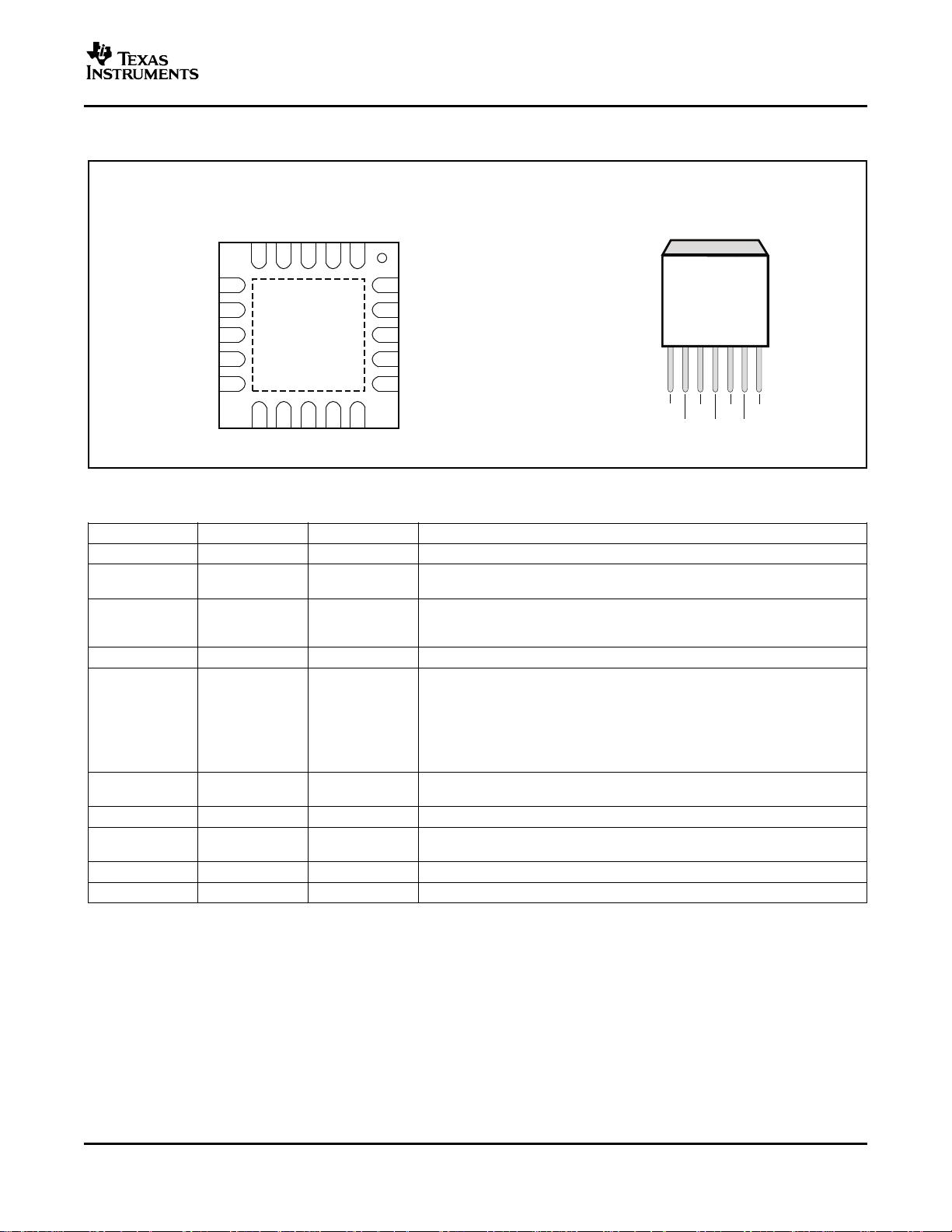
• Available in 5mm × 5mm × 1mm QFN and
other applications with specific start-up requirements.
DDPAK-7 Packages
A precision reference and error amplifier deliver 1%
• Open-Drain Power-Good (QFN only)
accuracy over load, line, temperature, and process.
• Active High Enable
Each LDO is stable with low-cost ceramic output
capacitors and the device is fully specified from
–40 ° C to +125 ° C. The TPS74401 is offered in a
• FPGA Applications
small (5mm × 5mm) QFN package, yielding a highly
compact total solution size. For applications that
• DSP Core and I/O Voltages
require additional power dissipation, the DDPAK
• Post-Regulation Applications
(KTW) package is also available.
• Applications with Special Start-Up Time or
Sequencing Requirements
• Hot-Swap and Inrush Controls
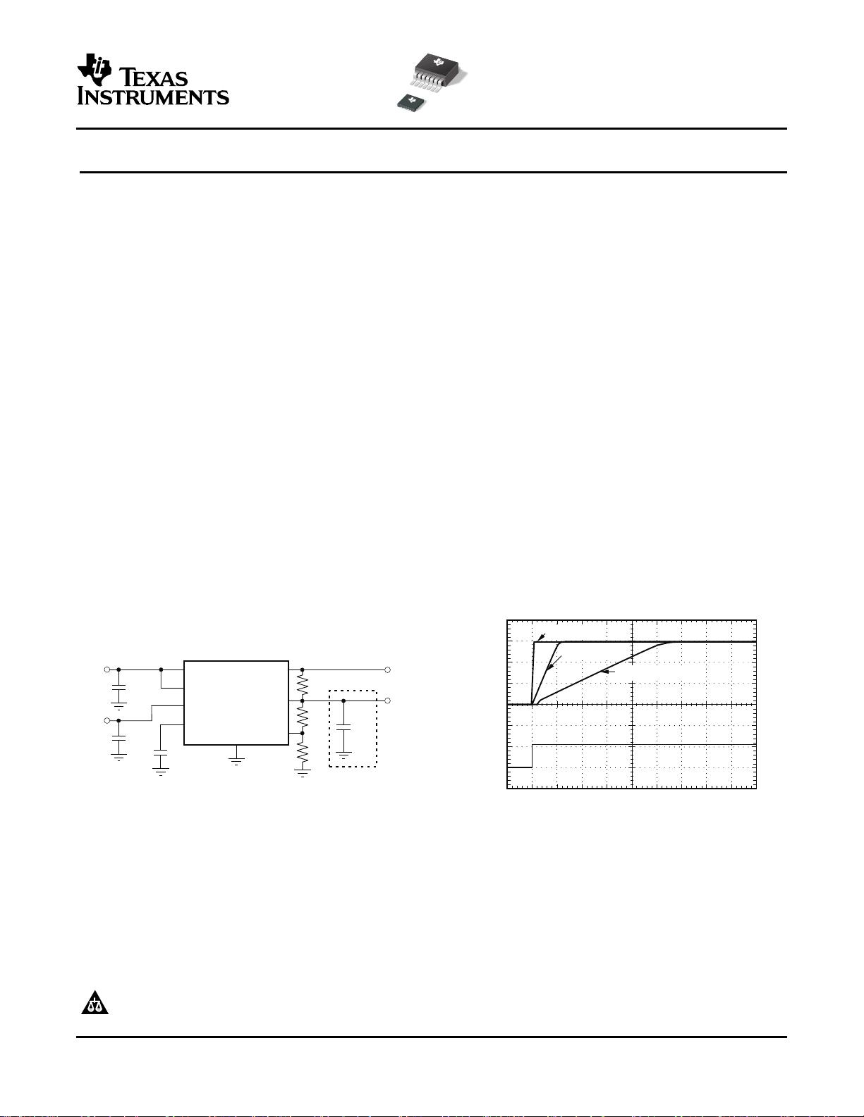
Figure 1. Typical Application Circuit
Figure 2. Turn-On Response
Please be aware that an important notice concerning availability, standard warranty, and use in critical applications of Texas
Instruments semiconductor products and disclaimers thereto appears at the end of this data sheet.
All trademarks are the property of their respective owners.
PRODUCTION DATA information is current as of publication date.
Copyright © 2005–2006, Texas Instruments Incorporated
Products conform to specifications per the terms of the Texas
Instruments standard warranty. Production processing does not
necessarily include testing of all parameters.
www.ti.com
ABSOLUTE MAXIMUM RATINGS
(1)
DISSIPATION RATINGS
TPS74401
SBVS066D – DECEMBER 2005 – REVISED AUGUST 2006
This integrated circuit can be damaged by ESD. Texas Instruments recommends that all integrated circuits be handled with
appropriate precautions. Failure to observe proper handling and installation procedures can cause damage.
ESD damage can range from subtle performance degradation to complete device failure. Precision integrated circuits may be
more susceptible to damage because very small parametric changes could cause the device not to meet its published
specifications.
ORDERING INFORMATION
(1)
PRODUCT V
OUT
(2)
TPS744 xxyyyz XX is nominal output voltage (for example, 12 = 1.2V, 15 = 1.5V, 01 = Adjustable).
(3)
YYY is package designator.
Z is package quantity.
(1) For the most current package and ordering information see the Package Option Addendum at the end of this document, or see the TI
website at www.ti.com .
(2) Output voltages from 0.9V to 1.5V in 50mV increments and 1.5V to 3.6V in 100mV increments are available through the use of
innovative factory EEPROM programming; minimum order quantities may apply. Contact factory for details and availability.
(3) For fixed 0.8V operation, tie FB to OUT.
At T
J
= –40 ° C to +125 ° C, unless otherwise noted. All voltages are with respect to GND.
TPS74401 UNIT
V
IN
, V
BIAS
input voltage range –0.3 to +6 V
V
EN
enable voltage range –0.3 to +6 V
V
PG
power-good voltage range –0.3 to +6 V
V
SS
SS pin voltage range –0.3 to +6 V
V
FB
feedback pin voltage range –0.3 to +6 V
V
OUT
output voltage range –0.3 to V
IN
+ 0.3 V
I
OUT
maximum output current Internally limited
Output short circuit duration Indefinite
P
DISS
continuous total power dissipation See Dissipation Ratings Table
T
J
operating junction temperature range –40 to +125 ° C
T
STG
storage junction temperature range –55 to +150 ° C
(1) Stresses beyond those listed under Absolute Maximum Ratings may cause permanent damage to the device. These are stress ratings
only and functional operation of the device at these conditions is not implied. Exposure to absolute-maximum-rated conditions for
extended periods may affect device reliability.
T
A
< +25 ° C DERATING FACTOR
PACKAGE θ
JA
θ
JC
POWER RATING ABOVE T
A
= +25 ° C
RGW (QFN)
(1)
36.5 ° C/W 4.05 ° C/W 2.74W 27.4mW/ ° C
KTW (DDPAK)
(2)
18.8 ° C/W 2.32 ° C/W 5.32W 53.2mW/ ° C
(1) See Figure 32 for PCB layout description.
(2) See Figure 35 for PCB layout description.
2
Submit Documentation Feedback
www.ti.com
ELECTRICAL CHARACTERISTICS
TPS74401
SBVS066D – DECEMBER 2005 – REVISED AUGUST 2006
At V
EN
= 1.1V, V
IN
= V
OUT
+ 0.3V, C
IN
= C
BIAS
= 0.1 µ F, C
OUT
= 10 µ F, I
OUT
= 50mA, V
BIAS
= 5.0V, and T
J
= –40 ° C to +125 ° C,
unless otherwise noted. Typical values are at T
J
= +25 ° C.
TPS74401
PARAMETER TEST CONDITIONS MIN TYP MAX UNIT
V
IN
Input voltage range V
OUT
+ V
DO
5.5 V
V
BIAS
Bias pin voltage range 2.375 5.25 V
V
REF
Internal reference (Adj.) T
J
= +25 ° C 0.796 0.8 0.804 V
Output voltage range V
IN
= 5V, I
OUT
= 1.5A, V
BIAS
= 5V V
REF
3.6 V
V
OUT
Accuracy
(1)
2.97V ≤ V
BIAS
≤ 5.25V, 50mA ≤ I
OUT
≤ 3.0A –1 ± 0.2 +1 %
V
OUT (NOM)
+ 0.3 ≤ V
IN
≤ 5.5V, QFN 0.0005 0.05
V
OUT
/V
IN
Line regulation %/V
V
OUT (NOM)
+ 0.3 ≤ V
IN
≤ 5.5V, DDPAK 0.0005 0.06
0mA ≤ I
OUT
≤ 50mA 0.013 %/mA
V
OUT
/I
OUT
Load regulation
50mA ≤ I
OUT
≤ 3.0A 0.03 %/A
I
OUT
= 3.0A, V
BIAS
– V
OUT (NOM)
≥ 1.62V, QFN 115 195
V
IN
dropout voltage
(2)
mV
I
OUT
= 3.0A, V
BIAS
– V
OUT (NOM)
≥ 1.62V,
V
DO
120 240
DDPAK
V
BIAS
dropout voltage
(2)
I
OUT
= 3.0A, V
IN
= V
BIAS
1.62 V
V
OUT
= 80% × V
OUT (NOM)
, QFN 3.8 6.0
I
CL
Current limit A
V
OUT
= 80% × V
OUT (NOM)
, DDPAK 3.5 6.0
I
BIAS
Bias pin current I
OUT
= 0mA to 3.0A 2 4 mA
Shutdown supply current
I
SHDN
V
EN
≤ 0.4V 1 100 µ A
(V
IN
)
I
FB
Feedback pin current
(3)
I
OUT
= 50mA to 3.0A –250 95 250 nA
1kHz, I
OUT
= 1.5A, V
IN
= 1.8V, V
OUT
= 1.5V 73
Power-supply rejection
dB
800kHz, I
OUT
= 1.5A, V
IN
= 1.8V,
(V
IN
to V
OUT
)
42
V
OUT
= 1.5V
PSRR
1kHz, I
OUT
= 1.5A, V
IN
= 1.8V, V
OUT
= 1.5V 62
Power-supply rejection
dB
800kHz, I
OUT
= 1.5A, V
IN
= 1.8V,
(V
BIAS
to V
OUT
)
50
V
OUT
= 1.5V
100Hz to 100kHz, I
OUT
= 1.5A,
Noise Output noise voltage 16 × V
OUT
µ V
RMS
C
SS
= 0.001 µ F
%V
OUT
droop during load
V
TRAN
I
OUT
= 100mA to 3.0A at 1A/ µ s, C
OUT
= 0 µ F 4 %V
OUT
transient
t
STR
Minimum startup time I
OUT
= 1.5A, C
SS
= open 100 µ s
I
SS
Soft-start charging current V
SS
= 0.4V 0.5 0.73 1 µ A
V
EN, HI
Enable input high level 1.1 5.5 V
V
EN, LO
Enable input low level 0 0.4 V
V
EN, HYS
Enable pin hysteresis 50 mV
V
EN, DG
Enable pin deglitch time 20 µ s
I
EN
Enable pin current V
EN
= 5V 0.1 1 µ A
V
IT
PG trip threshold V
OUT
decreasing 86.5 90 93.5 %V
OUT
V
HYS
PG trip hysteresis 3 %V
OUT
V
PG, LO
PG output low voltage I
PG
= 1mA (sinking), V
OUT
< V
IT
0.3 V
I
PG, LKG
PG leakage current V
PG
= 5.25V, V
OUT
> V
IT
0.03 1 µ A
Operating junction
T
J
–40 +125 ° C
temperature
Shutdown, temperature increasing +155
Thermal shutdown
T
SD
° C
temperature
Reset, temperature decreasing +140
(1) Adjustable devices tested at 0.8V; external resistor tolerance is not taken into account.
(2) Dropout is defined as the voltage from the input to V
OUT
when V
OUT
is 2% below nominal.
(3) I
FB
current flow is out of the device.
3
Submit Documentation Feedback
www.ti.com
BLOCK DIAGRAM
Thermal
Limit
Soft-Start
Discharge
OUT
V
OUT
FB
PG
IN
BIAS
SS
EN
Hysteresis
andDe-Glitch
Current
Limit
UVLO
0.73 Am
0.8V
Reference
0.9V ´ V
REF
GND
C
SS
R
1
R
2
V =0.8x( )
OUT
1+
R
1
R
2
TPS74401
SBVS066D – DECEMBER 2005 – REVISED AUGUST 2006
Table 1. Standard 1% Resistor Values for Programming the Output Voltage
(1)
R
1
(k Ω ) R
2
(k Ω ) V
OUT
(V)
Short Open 0.8
0.619 4.99 0.9
1.13 4.53 1.0
1.37 4.42 1.05
1.87 4.99 1.1
2.49 4.99 1.2
4.12 4.75 1.5
3.57 2.87 1.8
3.57 1.69 2.5
3.57 1.15 3.3
(1) V
OUT
= 0.8 × (1 + R1/R2)
Table 2. Standard Capacitor Values for Programming the Soft-Start Time
(1)
C
SS
SOFT-START TIME
Open 0.1ms
470pF 0.5ms
1000pF 1ms
4700pF 5ms
0.01 µ F 10ms
0.015 µ F 16ms
(1) t
SS
(s) = 0.8 × C
SS
(F)/7.3 × 10
–7
4
Submit Documentation Feedback
www.ti.com
5 5QFN(RGW)´
Package TopView¾
IN
IN
IN
PG
BIAS
OUT
OUT
OUT
NC
FB
TPS74401
IN
EN
11
GND
12
NC
13
NC
14
SS
15
6
7
8
9
10
20
19
18
17
16
5
NC4
NC3
NC2
OUT1
GND
7-Lead
DDPAK(KTW)
Surface-Mount
OUT
GND
BIAS
IN
FB
SS
1 2 3 4
5
6
EN
7
PIN DESCRIPTIONS
TPS74401
SBVS066D – DECEMBER 2005 – REVISED AUGUST 2006
NAME KTW (DDPAK) RGW (QFN) DESCRIPTION
IN 5 5–8 Unregulated input to the device.
Enable pin. Driving this pin high enables the regulator. Driving this pin low puts
EN 7 11
the regulator into shutdown mode. This pin must not be left floating.
SS 1 15 Soft-Start pin. A capacitor connected on this pin to ground sets the start-up
time. If this pin is left floating, the regulator output soft-start ramp time is
typically 100 µ s.
BIAS 6 10 Bias input voltage for error amplifier, reference, and internal control circuits.
Power-Good (PG) is an open-drain, active-high output that indicates the status
of V
OUT
. When V
OUT
exceeds the PG trip threshold, the PG pin goes into a
high-impedance state. When V
OUT
is below this threshold the pin is driven to a
PG N/A 9 low-impedance state. A pull-up resistor from 10k Ω to 1M Ω should be
connected from this pin to a supply up to 5.5V. The supply can be higher than
the input voltage. Alternatively, the PG pin can be left floating if output
monitoring is not necessary.
This pin is the feedback connection to the center tap of an external resistor
FB 2 16
divider network that sets the output voltage. This pin must not be left floating.
OUT 3 1, 18–20 Regulated output voltage. No capacitor is required on this pin for stability.
No connection. This pin can be left floating or connected to GND to allow better
NC N/A 2–4, 13, 14, 17
thermal contact to the top-side plane.
GND 4 12 Ground
PAD/TAB Should be soldered to the ground plane for increased thermal performance.
5
Submit Documentation Feedback
剩余21页未读,继续阅读
月半不知愁
- 粉丝: 1
- 资源: 6
上传资源 快速赚钱
- 我的内容管理 展开
- 我的资源 快来上传第一个资源
- 我的收益 登录查看自己的收益
- 我的积分 登录查看自己的积分
- 我的C币 登录后查看C币余额
- 我的收藏
- 我的下载
- 下载帮助
安全验证
文档复制为VIP权益,开通VIP直接复制
信息提交成功
评论0