没有合适的资源?快使用搜索试试~ 我知道了~
台达可编程控制器(PLC)DVP32ES2-C安装说明.pdf
5星 · 超过95%的资源 需积分: 50 11 下载量 20 浏览量
2019-09-12
23:42:38
上传
评论
收藏 941KB PDF 举报
温馨提示
试读
20页
台达可编程控制器(PLC)DVP32ES2-C安装说明pdf,台达可编程控制器(PLC)DVP32ES2-C安装说明:此主机提供32 点数输入/输出(16 点数字量输入、16 点数字量输出及内建CANopen 网络),含主机最大输入/输出扩展最多可达256 点。另依主机输入/输出点数、电源、数字量输入/输出与模拟量输入/输出模块搭配使用,可满足各种应用场合。
资源推荐
资源详情
资源评论
50
12
6
171
00
-
3
2
00
2012
-
03
-
02
- 1 -
………………………………………………………………… ENGLISH …………………………………………………………………
Thank you for choosing Delta’s DVP-ES2 series PLC. DVP-ES2 series MPU provides
32 points (16 points digital Input, 16 points digital Output and built-in CANopen). The
maximum I/O points including those on the MPU are 256 points. DVP-ES2 can be used
for various applications with different I/O points, power supply, digital I/O and analog I/O
modules.
a This instruction sheet provides only information on the electrical specification,
general functions, installation and wiring. For detailed program design and applicable
instructions for DVP-ES2, please refer to “DVP-ES2 Operation Manual:
Programming”. For details on the optional peripheral, please refer to the instruction
sheet enclosed in the package.
a DVP-ES2 series PLC is an OPEN TYPE device and therefore should be installed in
an enclosure free of airborne dust, humidity, electric shock and vibration. The
enclosure should prevent non-maintenance staff from operating the device (e.g. key
or specific tools are required for operating the enclosure) in case danger and damage
on the device may occur.
a DO NOT connect the input AC power supply to any of the I/O terminals; otherwise
serious damage may occur. Check all the wiring again before switching on the power.
Make sure the ground terminal is correctly grounded in order to prevent
electromagnetic interference.
Product Profile & Dimension
Removable I/O term inal block
Direct mounting hole
Mounting slot
(35mm)
COM1 Communication
(RS-232C)port
DIN rail clip
POWER, RUN ERROR indicators, & COM
I/O indicators
Run/Stop switch
I/O terminal No.
I/O module
portconnection
COM3 (CANopen)
I/O terminal No.
R
Output type
Model Name
I/O module clip
[ Figure 1 ]
DVP32ES2
16DI /16DO
COM2 (RS-485)
[ Figure 2 ]
106
98
90
78
61.5
110
137
145
Electrical Specifications
Model
Item
DVP32ES200RC DVP32ES200TC
Power supply
voltage
100 ~ 240VAC (-15% ~ 10%)
, 50/60Hz ±5%
- 2 -
Model
Item
DVP32ES200RC DVP32ES200TC
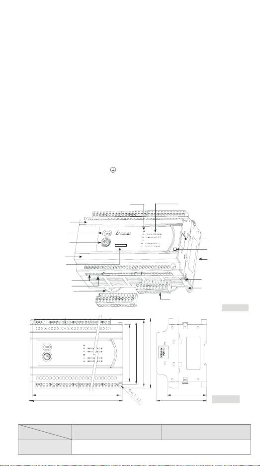
Connector European standard removable terminal block (Pin pitch: 5mm)
Operation
DVP-ES2 starts to run when the power rises to 95 ~ 100VAC and stops
when the power drops to 70VAC. If the power is suddenly cut off, the
MPU will continue running for 10ms.
Power supply fuse 2A/250VAC
Power consumption 30VA
DC24V current
output
500mA
Power supply
protection
DC24V output short circuit protection
Voltage withstand
1,500VAC (Primary-secondary)
, 1,500VAC (Primary-PE),
500VAC (Secondary-PE)
Insulation
resistance
> 5MΩ at 500VDC (between all I/O points and ground)
Noise immunity
ESD: 8KV Air Discharge
EFT: Power Line: 2KV, Digital I/O: 1KV, Analog & Communication I/O:
1KV
RS: 26MHz ~ 1GHz, 10V/m
Grounding
The diameter of grounding wire shall not be less than that of L, N
terminal of the power supply. (When many PLCs are in use at the same
time, please make sure every PLC is properly grounded.)
Environment
Operation: 0°C~55°C (temperature), 50~95% (humidity), pollution
degree 2
Storage: -25°C~70°C (temperature), 5~95% (humidity)
Agency approvals
UL508
European community EMC Directive 89/336/EEC and Low Voltage
Directive 73/23/EEC
Vibration/shock
immunity
International standards: IEC61131-2, IEC 68-2-6 (TEST Fc)/
IEC61131-2 & IEC 68-2-27 (TEST Ea)
Weight(g) 489 432
Input Point
Input No. X0 ~ X3 X4 ~ X7 X10 ~ X17
Type Digital input
Input type DC (SINK or SOURCE)
Input current 24VDC, 5mA
Input impedance 3.9kΩ 4.7kΩ
Max. frequency
100kHz 10kHz 60Hz
Off → On >15VDC
Action level
On → Off < 5VDC
Off → On < 2.5μs
< 20μs
< 10ms
Response time
On → Off < 5μs
< 50μs
< 15ms
Filter time X0 ~ X7 Adjustable within 0 ~ 20ms in D1020 (Default: 10ms)
Output Point
Output point type Relay-R Transistor-T
Output point number All Y0, Y2 Y1, Y3 Y4~Y17
Voltage specification < 250VAC, 30VDC
5 ~ 30VDC
#1
Max. frequency 1Hz 100kHz 10kHz 1kHz
Resistive 2A/1 point (5A/COM) 0.5A/1 point (4A/ZP)
Maximum load
Inductive
#2
15W (30VDC)
- 3 -
Output Point
Lamp 20WDC/100WAC 2.5W(30VDC)
Off → On < 2μs < 20μs < 100μs
Response time
On → Off
Approx .10ms
< 3μs < 30μs < 100μs
#1: UP, ZP must work with external auxiliary power supply 24VDC (-15% ~ +20%), rated
consumption approx. 1mA/point.
#2: Life curves
Contact
Current(A)
20
0.5
0.1
0.2
30
50
0.3 0.7
12
200
300
500
100
1,000
2,000
3,000
O
p
e
r
a
t
i
o
n
(
X
1
0
)
3
120VAC Resistive
30VDC Inductive(t=7ms)
240VAC Inductive(cos 0.4)ψ=
120VAC Inductive(cos =0.4)ψ
30VDC
Inductive
( t=4 0ms)
[ Figure 3 ]
CANopen Specifications
Communication type
PDO, SDO, SYNC (synchronous transmission), Emergency
(emergency transmission), NMT
Serial communication
speed
Supports 20K、50K、125K、250K、500K、1M bps (bit/second)
Station address 1~127
Electrical isolation
500V DC
Communication cable
Users are suggested to use the Delta standard cable TAP-CB01
or TAP-CB02, and the communication cable should be kept away
from the power cable.
Control flag M1349
ON: (Default) Communication is enabled.
OFF: Communication is disabled.
Note 1: The station addresses of slaves connected to DVP32ES2-C as a master only can range
between 1 and 16. Besides, the station address of the master and that of the slave can
not be the same.
Note 2: The network function of CANopen should be set by means of CANopen Builder. Please
refer to the software manual for more information about the setting.
Installation
Please install the PLC in an enclosure with
sufficient space around it to allow heat dissipation,
as shown in the figure.
y Direct Mounting: Please use M4 screw
according to the dimension of the product.
y DIN Rail Mounting: When mounting the PLC to
35mm DIN rail, be sure to use the retaining clip to stop any side-to-side movement o
f
the PLC and reduce the chance of wires being loose. The retaining clip is at the
bottom of the PLC. To secure the PLC to DIN rail, pull down the clip, place it onto the
rail and gently push it up. To remove the PLC, pull the retaining clip down with a fla
t
screwdriver and gently remove the PLC from DIN rail.
Wiring
1. Use the 12-24 AWG single-core bare wire or the multi-core wire for the I/O wiring.
剩余19页未读,继续阅读
资源评论
- 小明斗2023-07-24文件中给出了步骤和示意图,让用户能够轻松理解并完成安装。
- 城北伯庸2023-07-24这个文件解释了如何正确安装台达可编程控制器,对于解决安装过程中的疑惑非常有帮助。
- 我要WhatYouNeed2023-07-24安装说明文件中提供的细节十分全面,可以帮助用户避免一些常见的错误和问题。
- 曹多鱼2023-07-24这份文件的语言简洁明了,没有使用专业术语,适合各种技术水平的用户阅读。
- 代码深渊漫步者2023-07-24这份安装说明文件详细清晰,对于初学者来说非常友好。
weixin_38743481
- 粉丝: 694
- 资源: 4万+
上传资源 快速赚钱
- 我的内容管理 展开
- 我的资源 快来上传第一个资源
- 我的收益 登录查看自己的收益
- 我的积分 登录查看自己的积分
- 我的C币 登录后查看C币余额
- 我的收藏
- 我的下载
- 下载帮助
安全验证
文档复制为VIP权益,开通VIP直接复制
信息提交成功