没有合适的资源?快使用搜索试试~ 我知道了~
The DS1307 serial real-time clock (RTC) is a low-power, full binary-coded decima
资源详情
资源评论
资源推荐
1 of 14
REV: 100208
GENERAL DESCRIPTION
The DS1307 serial real-time clock (RTC) is a low-
power, full binary-coded decimal (BCD) clock/calendar
plus 56 bytes of NV SRAM. Address and data are
transferred serially through an I
2
C, bidirectional bus.
The clock/calendar provides seconds, minutes, hours,
day, date, month, and year information. The end of
the month date is automatically adjusted for months
with fewer than 31 days, including corrections for leap
year. The clock operates in either the 24-hour or 12-
hour format with AM/PM indicator. The DS1307 has a
built-in power-sense circuit that detects power failures
and automatically switches to the backup supply.
Timekeeping operation continues while the part
operates from the backup supply.
TYPICAL OPERATING CIRCUIT
FEATURES
Real-Time Clock (RTC) Counts Seconds,
Minutes, Hours, Date of the Month, Month, Day of
the week, and Year with Leap-Year
Compensation Valid Up to 2100
56-Byte, Battery-Backed, General-Purpose RAM
with Unlimited Writes
I
2
C Serial Interface
Programmable Square-Wave Output Signal
Automatic Power-Fail Detect and Switch Circuitry
Consumes Less than 500nA in Battery-Backup
Mode with Oscillator Running
Optional Industrial Temperature Range:
-40°C to +85°C
Available in 8-Pin Plastic DIP or SO
Underwriters Laboratories (UL) Recognized
PIN CONFIGURATIONS
V
CC
SCL
SDA
X1
X2
V
BAT
GND
SQW/OUT
V
CC
SCL
SDA
X1
X2
V
BAT
GND
SQW/OUT
PDIP (300 mils)SO (150 mils)
TOP VIEW
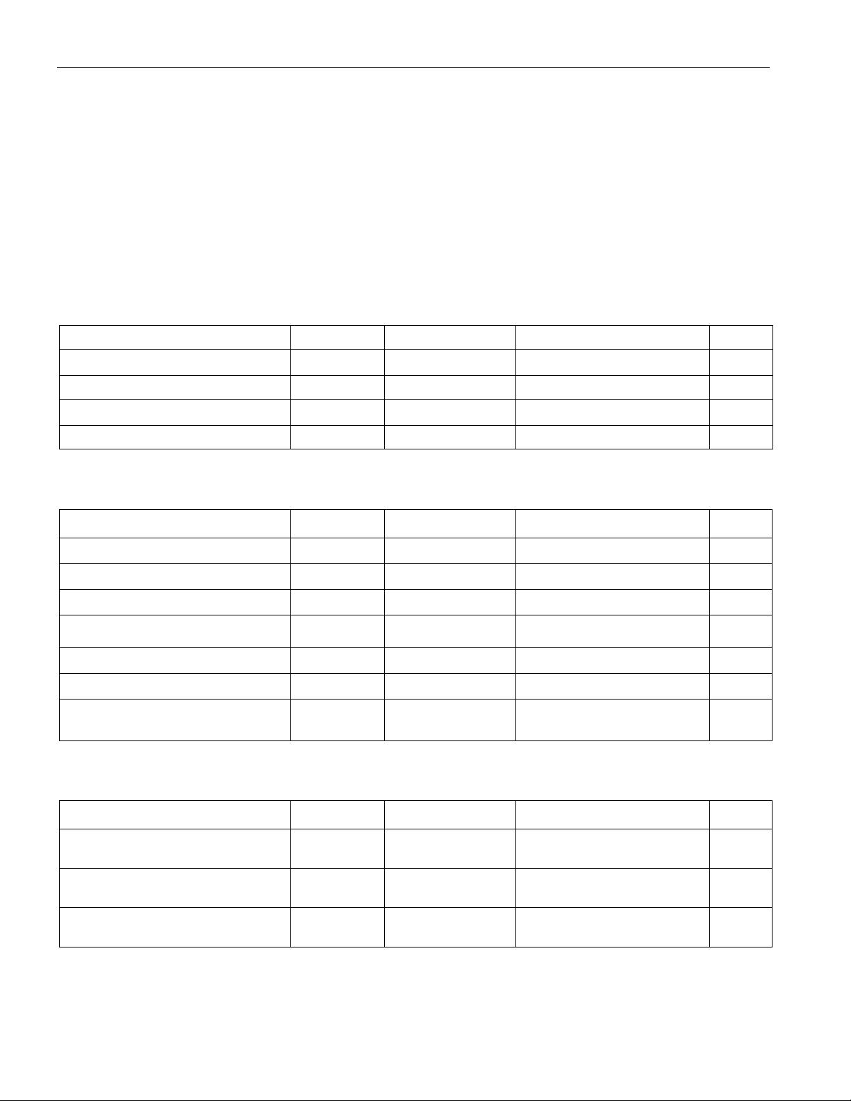
ORDERING INFORMATION
PART TEMP RANGE VOLTAGE (V) PIN-PACKAGE TOP MARK*
DS1307+
0°C to +70°C 5.0 8 PDIP (300 mils) DS1307
DS1307N+
-40°C to +85°C 5.0 8 PDIP (300 mils) DS1307N
DS1307Z+
0°C to +70°C 5.0 8 SO (150 mils) DS1307
DS1307ZN+
-40°C to +85°C 5.0 8 SO (150 mils) DS1307N
DS1307Z+T&R
0°C to +70°C 5.0 8 SO (150 mils) Tape and Reel DS1307
DS1307ZN+T&R
-40°C to +85°C 5.0 8 SO (150 mils) Tape and Reel DS1307N
+Denotes a lead-free/RoHS-compliant package.
*A “+” anywhere on the top mark indicates a lead-free package. An “N” anywhere on the top mark indicates an industrial temperature range
device.
DS130
CPU
V
CC
V
CC
V
CC
SDA
SCL
GND
X2 X1
V
CC
R
PU
R
PU
CRYSTAL
SQW/OUT
V
BAT
R
PU
= t
r
/C
b
DS1307
64 x 8, Serial, I
2
C Real-Time Clock
DS1307 64 x 8, Serial, I
2
C Real-Time Clock
2 of 14
ABSOLUTE MAXIMUM RATINGS
Voltage Range on Any Pin Relative to Ground ....................................................................................-0.5V to +7.0V
Operating Temperature Range (Noncondensing)
Commercial................................................................................................................................0°C to +70°C
Industrial ..................................................................................................................................-40°C to +85°C
Storage Temperature Range ............................................................................................................. -55°C to +125°C
Soldering Temperature (DIP, leads)........................................................................................+260°C for 10 seconds
Soldering Temperature (surface mount)…..……………………….Refer to the JPC/JEDEC J-STD-020 Specification.
Stresses beyond those listed under “Absolute Maximum Ratings” may cause permanent damage to the device. These are stress ratings only,
and functional operation of the device at these or any other conditions beyond those indicated in the operational sections of the specifications is
not implied. Exposure to the absolute maximum rating conditions for extended periods may affect device reliability.
RECOMMENDED DC OPERATING CONDITIONS
(T
A
= 0°C to +70°C, T
A
= -40°C to +85°C.) (Notes 1, 2)
PARAMETER SYMBOL CONDITIONS MIN TYP MAX UNITS
Supply Voltage V
CC
4.5 5.0 5.5 V
Logic 1 Input V
IH
2.2 V
CC
+ 0.3 V
Logic 0 Input V
IL
-0.3 +0.8 V
V
BAT
Battery Voltage V
BAT
2.0 3 3.5 V
DC ELECTRICAL CHARACTERISTICS
(V
CC
= 4.5V to 5.5V; T
A
= 0°C to +70°C, T
A
= -40°C to +85°C.) (Notes 1, 2)
PARAMETER SYMBOL CONDITIONS MIN TYP MAX UNITS
Input Leakage (SCL) I
LI
-1 1
μA
I/O Leakage (SDA, SQW/OUT) I
LO
-1 1
μA
Logic 0 Output (I
OL
= 5mA) V
OL
0.4 V
Active Supply Current
(f
SCL
= 100kHz)
I
CCA
1.5 mA
Standby Current I
CCS
(Note 3) 200
μA
V
BAT
Leakage Current I
BATLKG
5 50 nA
Power-Fail Voltage (V
BAT
= 3.0V) V
PF
1.216 x
V
BAT
1.25 x
V
BAT
1.284 x
V
BAT
V
DC ELECTRICAL CHARACTERISTICS
(V
CC
= 0V, V
BAT
= 3.0V; T
A
= 0°C to +70°C, T
A
= -40°C to +85°C.) (Notes 1, 2)
PARAMETER SYMBOL CONDITIONS MIN TYP MAX UNITS
V
BAT
Current (OSC ON);
SQW/OUT OFF
I
BAT1
300 500 nA
V
BAT
Current (OSC ON);
SQW/OUT ON (32kHz)
I
BAT2
480 800 nA
V
BAT
Data-Retention Current
(Oscillator Off)
I
BATDR
10 100 nA
WARNING: Negative undershoots below -0.3V while the part is in battery-backed mode may cause loss of data.
DS1307 64 x 8, Serial, I
2
C Real-Time Clock
3 of 14
AC ELECTRICAL CHARACTERISTICS
(V
CC
= 4.5V to 5.5V; T
A
= 0°C to +70°C, T
A
= -40°C to +85°C.)
PARAMETER SYMBOL CONDITIONS MIN TYP MAX UNITS
SCL Clock Frequency f
SCL
0 100 kHz
Bus Free Time Between a STOP and
START Condition
t
BUF
4.7
μs
Hold Time (Repeated) START
Condition
t
HD:STA
(Note 4) 4.0
μs
LOW Period of SCL Clock t
LOW
4.7
μs
HIGH Period of SCL Clock t
HIGH
4.0
μs
Setup Time for a Repeated START
Condition
t
SU:STA
4.7
μs
Data Hold Time t
HD:DAT
0
μs
Data Setup Time t
SU:DAT
(Notes 5, 6) 250 ns
Rise Time of Both SDA and SCL
Signals
t
R
1000 ns
Fall Time of Both SDA and SCL
Signals
t
F
300 ns
Setup Time for STOP Condition t
SU:STO
4.7
μs
CAPACITANCE
(T
A
= +25°C)
PARAMETER SYMBOL CONDITIONS MIN TYP MAX UNITS
Pin Capacitance (SDA, SCL) C
I/O
10 pF
Capacitance Load for Each Bus
Line
C
B
(Note 7) 400 pF
Note 1:
All voltages are referenced to ground.
Note 2:
Limits at -40°C are guaranteed by design and are not production tested.
Note 3:
I
CCS
specified with V
CC
= 5.0V and SDA, SCL = 5.0V.
Note 4:
After this period, the first clock pulse is generated.
Note 5:
A device must internally provide a hold time of at least 300ns for the SDA signal (referred to the V
IH(MIN)
of the SCL
signal) to bridge the undefined region of the falling edge of SCL.
Note 6:
The maximum t
HD:DAT
only has to be met if the device does not stretch the LOW period (t
LOW
) of the SCL signal.
Note 7:
C
B
—total capacitance of one bus line in pF.
剩余13页未读,继续阅读
张盛锋
- 粉丝: 26
- 资源: 297
上传资源 快速赚钱
- 我的内容管理 展开
- 我的资源 快来上传第一个资源
- 我的收益 登录查看自己的收益
- 我的积分 登录查看自己的积分
- 我的C币 登录后查看C币余额
- 我的收藏
- 我的下载
- 下载帮助
最新资源
- AutoCAD电气图纸建筑电气开关柜常用cad图纸
- 使用ASP.NET Core和Entity Framework Core来构建一个基本的进销存系统.rar
- 深度学习经典数据集+FER2013面部表情识别+附带使用方法的python代码
- Python中,要实现连接多个相机并识别多个二维码.rar
- 使用FFT算法对一个信号进行分析.rar
- 171cms游戏应用下载系统源码.zip
- 基于jsp+servlet+mysql蛋糕甜品店购物网站源码+数据库(期末大作业).zip
- Java项目:在线蛋糕商城系统(java+jsp+mysql)源码+数据库+期末大作业.zip
- ZapyaClient10_7-1.apk
- 织梦cms站长导航网站源码.zip
资源上传下载、课程学习等过程中有任何疑问或建议,欢迎提出宝贵意见哦~我们会及时处理!
点击此处反馈
安全验证
文档复制为VIP权益,开通VIP直接复制
信息提交成功
评论0