DS18B20英文手册
需积分: 0 200 浏览量
2022-08-06
10:23:32
上传
评论 1
收藏 383KB PDF 举报

1 of 21 050102
FEATURES
§ Unique 1-Wire
®
interface requires only one
port pin for communication
§ Each device has a unique 64-bit serial code
stored in an onboard ROM
§ Multidrop capability simplifies distributed
temperature sensing applications
§ Requires no external components
§ Can be powered from data line. Power supply
range is 3.0V to 5.5V
§ Measures temperatures from –55°C to
+125°C (–67°F to +257°F)
§ ±0.5°C accuracy from –10°C to +85°C
§ Thermometer resolution is user-selectable
from 9 to 12 bits
§ Converts temperature to 12-bit digital word in
750ms (max.)
§ User-definable nonvolatile (NV) alarm
settings
§ Alarm search command identifies and
addresses devices whose temperature is
outside of programmed limits (temperature
alarm condition)
§ Available in 8-pin SO (150mil), 8-pin mSOP,
and 3-pin TO-92 packages
§ Software compatible with the DS1822
§ Applications include thermostatic controls,
industrial systems, consumer products,
thermometers, or any thermally sensitive
system
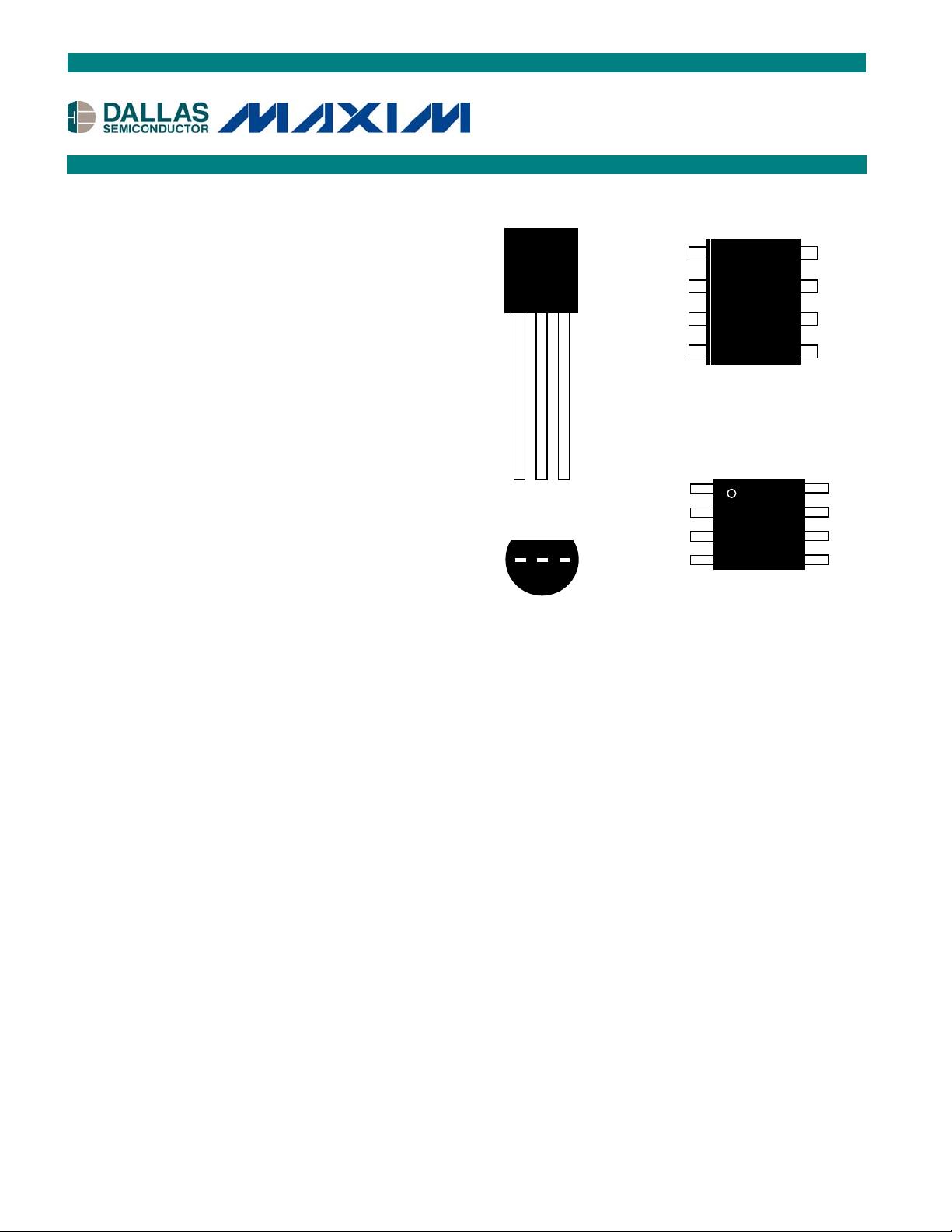
PIN ASSIGNMENT
PIN DESCRIPTION
GND - Ground
DQ - Data In/Out
V
DD
- Power Supply Voltage
NC - No Connect
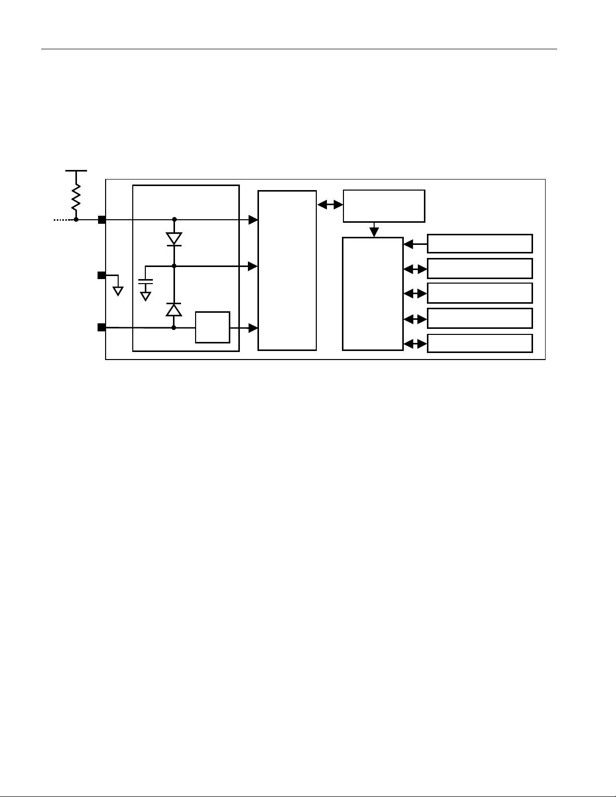
DESCRIPTION
The DS18B20 Digital Thermometer provides 9 to 12–bit centigrade temperature measurements and has
an alarm function with nonvolatile user-programmable upper and lower trigger points. The DS18B20
communicates over a 1-Wire bus that by definition requires only one data line (and ground) for
communication with a central microprocessor. It has an operating temperature range of –55°C to +125°C
and is accurate to ±0.5°C over the range of –10°C to +85°C. In addition, the DS18B20 can derive power
directly from the data line (“parasite power”), eliminating the need for an external power supply.
Each DS18B20 has a unique 64-bit serial code, which allows multiple DS18B20s to function on the same
1–wire bus; thus, it is simple to use one microprocessor to control many DS18B20s distributed over a
large area. Applications that can benefit from this feature include HVAC environmental controls,
temperature monitoring systems inside buildings, equipment or machinery, and process monitoring and
control systems.
DS18B20
Programmable Resolution
1-Wire Digital Thermomete
r
www.maxim
-
ic.c
om
8-Pin 150mil SO
(DS18B20Z)
TO-92
(
DS18B20
)
1
(
BOTTOM VIEW
)
2 3
DALLAS
18B20
1
GND
DQ
V
DD
2 3
N
C
NC
NC
NC
GND
DQ
V
DD
N
C
6
8
7
5
3
1
2
4
DALLAS
18B20
N
C
V
DD
NC
NC
NC
GND
NC
D
Q
6
8
7
5
3
1
2
4
18B20
8-Pin
m
SOP
(
DS18B20U
)
1-Wire is a registered trademark of Dallas Semiconductor.
剩余20页未读,继续阅读


评论0