没有合适的资源?快使用搜索试试~ 我知道了~
资源推荐
资源详情
资源评论
Field Programmable Gate Arrays (FPGA) and Complex Programmable Logic Devices (CPLD)
Power Management Reference Guide
for Altera
®
FPGAs and CPLDs
3Q 2005
TI Power Solutions: Power Behind Your Designs
FPGA/CPLD
DC/DC
Converters
DC/DC
Converters
DC/DC
Converters
Supply Voltage
Supervisor
SD RAM
and
DATA CONV.
V
CCINT
V
CCIO
Input
Supply
Power Design Library 2
Stratix
®
II
Stratix
®
GX
Stratix
®
Cyclone
™
MAX
®
II
Altera Power Guidelines 3
Recommended DC/DC Converters 4
Product Selection Guides 18-19
Active Bus Termination 20-21
Inside
➔
www.ti.com/alterafpga
Technology for Innovators
TM
Technology for Innovators
TM
Texas Instruments 3Q 2005 Power Management FPGA/CPLD Reference Guide
2
Power Management FPGA and CPLD Reference Guide
TI’s Power Management Reference Designs for Altera FPGAs and CPLDs
2
Design Library Table of Contents
➔
Complete schematics, bills of materials and additional designs available at:
www.ti.com/alterafpga
Questions? fpgasupport@list.ti.com
Important Design Considerations..............................................................................................................................................................................................................5
Stratix II, Stratix GX/Stratix/Cyclone FPGA Core and I/O Power Solutions*
3.3-V or 5-V Input Supplies
800-mA Core and I/O, Dual Low Dropout (LDO) Linear Regulator (TPS70402) Solution................................................................................................................................6
1-A Core and I/O, Independent LDOs (Two TPS725xx) Solution ....................................................................................................................................................................6
1.5-A Core (TPS54110 DC/DC Converter), 1.5-A I/O (TPS786xx LDO) Solution; 3-A Core Adaptable ...........................................................................................................7
3-A Core (TPS64203 DC/DC Controller), 1.5-A I/O (TPS78633 LDO) Solution................................................................................................................................................7
3-A Core and I/O (Two TPS64203 DC/DC Controllers) Solution .....................................................................................................................................................................8
6-A Core and I/O (Two TPS54610 DC/DC Converters) Solution; 8-A, 9-A Adaptable....................................................................................................................................8
6-A Core and I/O (Two PTH05050 Modules) Solution; 10-A, 15-A, 22-A, 30-A Adaptable ...........................................................................................................................9
20-A Core and I/O (Two TPS40021 DC/DC Controllers) Solution ...................................................................................................................................................................9
20-A Core (TPS40007 DC/DC Controller) and 6-A I/O (TPS54610 DC/DC Converter) Solution; 8-A, 9-A I/O Adaptable............................................................................10
12-V Input Supplies
26-A Core (PTH12030 Module) and 12-A I/O (PTH12010 Module) Solution; 6-A, 10-A, 18-A Adaptable...................................................................................................10
3-A Core and I/O (Two TPS54350 DC/DC Converters) Solution....................................................................................................................................................................11
6-A Core and I/O (Two PTH12050 Modules) Solution; 10-A, 12-A, 18-A, 26-A Adaptable .........................................................................................................................11
15-A Core and 10 A I/O, (Two TPS40055 DC/DC Controllers) Solution........................................................................................................................................................12
Stratix II V
CCPD
Power Solution*
TPS73633 LDO Solution.................................................................................................................................................................................................................................12
PLL and Transceiver Power Solutions*
Stratix II/Stratix GX/Stratix PLL Supply.........................................................................................................................................................................................................13
Cyclone PLL Supplies .....................................................................................................................................................................................................................................13
Stratix II/Stratix GX/ Stratix PLL OUT Supply ...............................................................................................................................................................................................14
Stratix GX Transceivers Supplies...................................................................................................................................................................................................................14
MAX II CPLD Power Solutions*
3.3-V or 5-V Input Supplies
150-mA Core and I/O (Two TPS731xx LDOs) Solution; 250-mA, 400-mA Adaptable...................................................................................................................................15
1.5-A LDO (TPS78633) Powering Both Core and I/O.....................................................................................................................................................................................15
400-mA Core (TPS73633 LDO) and 1.2-A I/O (TPS62042 DC/DC Converter) Solution.................................................................................................................................16
12-V Input Supplies
3-A DC/DC Converter (TPS54350) Powering Both Core and I/O...................................................................................................................................................................16
Appendices
Notes..............................................................................................................................................................................................................................................................17
Texas Instruments Power Management Products Selection Guide..............................................................................................................................................................18
Active Bus Termination Solutions (DDR/QDR/GTL/SSTL/HSTL)...................................................................................................................................................................20
*Current ratings shown refer to the total load on the power supply from the system, including the FPGA or CPLD and surrounding components.
Stratix II FPGA Power Guidelines
V
CCINT
(core voltage) 1.15 V min, 1.2 V typ, 1.25 V max
I
CCINT
(core current) To ensure correct selection of power
management circuitry it is recommended to use
Altera’s PowerPlay Power Estimation Tools to
obtain accurate results. Tools are available to
help determine power consumption before and
during the design process. More information on
these tools is available from Altera’s website:
www.altera.com/support/devices/estimator/
pow-powerplay.html
V
CCPD
(internal buffer voltage) 3.3 V typ
V
CCIO
(input/output voltages) 3.3 V, 2.5 V, 1.8 V and/or 1.5 V
I
CCIO
(input/output current) Up to 8 I/O banks @ up to 1.25 A each
Stratix and Stratix GX FPGA Power Guidelines
V
CCINT
(core) 1.5 V ± 5%
I
CCINT
(core) 250 mA to 10 A
I
CCINT
inrush to start-up EP1S10, EP1SGX10: 250 mA typ, 700 mA max
EP1S20: 400 mA typ, 1,200 mA max
EP1S25, EP1SGX25: 500 mA typ, 1,500 mA max
EP1S40, EP1SGX40: 650 mA typ, 2,300 mA max
EP1S60: 800 mA typ, 2,600 mA max
EP1S80: 1,000 mA typ, 3,000 mA max
V
CCIO
(I/O) 3.3 V, 2.5 V, 1.8 V and/or 1.5 V
I
CCIO
(I/O) Up to 8 I/O banks @ 50 mA to 1.5 A each
V
CC_PLL_OUT
3.3 V, 2.5 V, 1.8 V and/or 1.5 V
I
CC_PLL_OUT
50 mA (max)
Digital
(1)
voltages above Analog voltages below
V
CCA_PLL
1.5 V ± 5%
I
CC_PLL
200 mA (max) per PLL
Up to 12 each with separate V
CC
and GND
Additional Stratix GX Power Guidelines
Digital Transceiver Voltage: VCCP, VCCG 1.5 V ± 5%
ICC_Transceiver 250 mA (max) per transceiver
4 transceivers per block
Up to 5 blocks per device
Analog Transceiver Voltage: VCCR, VCCT 1.5 V ± 5%
ICC_Transceiver 250 mA (max) per transceiver
4 transceivers per block
Up to 5 blocks per device
Analog Transmitter Voltage: VCCAQ 3.3 V ± 5%
50 mA (max) per transceiver block
33
➔
➔
Texas Instruments 3Q 2005 Power Management FPGA/CPLD Reference Guide
Power Management FPGA and CPLD Reference Guide
Introduction
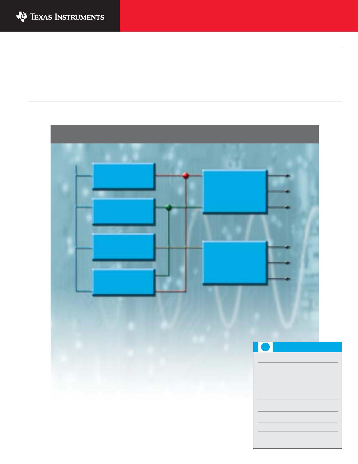
Texas Instruments (TI) works closely with Altera to recommend robust power solutions. On this page you will find a summary of the FPGA/CPLD
power guidelines. On page 2 is a comprehensive library of power designs. A listing of the TI DC/DC converter products that have been tested
and endorsed by Altera to power the listed devices is on page 4; schematics begin on page 6. Complete schematics and bill of materials (BOMs)
are available at www.ti.com/alterafpga. Please send questions to fpgasupport@list.ti.com.
This information is intended to provide the designer with a general understanding of the power guidelines of Altera FPGA/CPLD families in
typical applications. Please refer to the Altera Power Estimators, available at www.altera.com, for closer approximations specific to individual
FPGA/CPLD devices and applications.
Power Guidelines for Altera FPGAs and CPLDs
Cyclone FPGA Power Guidelines
V
CCINT
(core) 1.5 V ± 5%
I
CCINT
(core) 300 mA to 5 A
I
CCINT
inrush to start-up EC1C3: 300 mA max
EP1C4: 400 mA max
EP1C6: 500 mA max
EP1C12: 900 mA max
EP1C20: 1,200 mA max
V
CCIO
(I/O) 3.3 V, 2.5 V, 1.8 V and/or 1.5 V
I
CCIO
(I/O) Up to 4 I/O banks (50 mA to 1.5 A each)
Digital
(1)
voltages above Analog voltages below
V
CCA_PLL
(two) 1.5 V ± 5%
I
CC_PLL
200 mA (max) per PLL
MAX II CPLD Power Guidelines
V
CCINT
(core voltage) 2.375 V min, 2.5 V typ, 2.625 V max
(2.5 V or 3.3 V supported on all MAX II 3.00 V min, 3.3 V typ, 3.6 V max
without “G” ordering code. 1.8 V 1.71 V min, 1.8 V typ, 1.89 V max
supported with “G” ordering code.)
I
CCINT
(core current) EPM240: 30 mA typ, 75 mA max
EPM570: 40 mA typ, 125 mA max
EPM1270: 55 mA typ, 250 mA max
EPM2210: 75 mA typ, 400 mA max
I
CCINT
(inrush to start-up) 65 mA max
I
CCSTANDBY
12 mA typ
V
CCIO
(input/output voltages) 3.3 V, 2.5 V, 1.8 V and/or 1.5 V
I
CCIO
(input/output current) 25 to 50 mA each typ, 75 to 225 mA each max
(up to 4 I/O banks)
1
Digital voltages can be powered by linear or switching DC/DC converters. Linear regulators are recommended for analog voltages, for minimal noise.
4
Power Management FPGA and CPLD Reference Guide
TI Recommended DC/DC Converters For Powering Altera FPGAs and CPLDs
➔
➔
Texas Instruments 3Q 2005 Power Management FPGA/CPLD Reference Guide
Complete schematics available at:
www.ti.com/alterafpga
DC/DC Converter Selection Considerations
These recommended DC/DC converter products have been tested and endorsed by Altera to power the listed FPGAs. MAX II CPLD
recommendations are preliminary pending testing. Digital voltages can be powered by either linear or switching DC/DC regulators. For minimal
noise, linear regulators are recommended for analog voltages. Please see the selection guides on pages 18 and 19 for electrical specifics
of the recommended devices.
Stratix GX
FPGA
Stratix II
FPGA
Stratix
FPGA
Cyclone
FPGA
MAX II
CPLD
compensation, resulting in a smaller solution due
to the ability to minimize the inductor and use ceramic
capacitors
- Exhibit switching noise
- Up to 95% efficient, giving a much cooler solution than
a linear regulator, but due to the power dissipation in
the internal FETs, switching DC/DC converters support
only up to about 9 A
• Switching DC/DC Controllers
- More cost-effective than DC/DC converters, but
consume more board space and are more challenging
to implement as they require the addition of external
FETs
- Can support high-current applications, limited only
by the controller’s drive and the external FET’s power
dissipation capabilities
• Modules
- Easiest switching DC/DC solution available. The module
solution is complete, needing only the addition of an
input and output capacitor for increased transient
response
- Double-sided modules save board space
- Full environmental qualification and EMI reports
are available
• Low Dropout (LDO) Linear Regulators
- Easiest, smallest, and most cost-effective type of DC/DC
converter to implement
- Typically just require the addition of a small input
capacitor and output capacitor for stability
- Exhibit low noise and therefore are ideal for powering
analog voltages
- Recommended for low power applications only due to
generally low efficiency (LDO Eff = V
OUT
/V
IN
x 100%) and
resulting heat. Ensure the application does not violate
the regulator’s maximum allowable power dissipation.
Refer to TI Application Note SLVA118
‘Digital Designer’s
Guide to Linear Voltage Regulators and Thermal
Management’
for guidance.
- Low dropout performance needed to support small
V
IN
to V
OUT
voltage differential
• Switching DC/DC Converters
- Easiest, smallest, discrete IC, switching DC/DC solution
to implement due to integration of the FETs
- Require the addition of an inductor and capacitors for
the output filter
- Use fixed output voltage, internally compensated
devices to minimize component count and simplify
implementation
- Using adjustable output voltage TPS54xxx devices
instead of fixed output options allows for external
Digital Voltages Analog Voltages
Low Dropout Switching Switching Low Dropout
(LDO) DC/DC Converters DC/DC Controllers Switching (LDO)
Linear Regulators (Integrated FET) (External FET) DC/DC Modules Linear Regulators
to 1.5 A to 9 A to 20 A to 30 A to 1.5 A
TPS79xxx TPS79xxx
TPS786xx TPS54xxx TPS6420x PTH Series TPS786xx
TPS725xx TPS400xx TPS732/6xx
TPS703/4xx
TPS79xxx TPS79xxx
TPS786xx TPS54xxx TPS6420x PTH Series TPS786xx
TPS725xx TPS400xx TPS732/6xx
TPS703/4xx
TPS79xxx TPS79xxx
TPS786xx TPS54xxx TPS6420x PTH Series TPS786xx
TPS725xx TPS400xx TPS732/6xx
TPS703/4xx
TPS79xxx TPS79xxx
TPS786xx TPS54xxx TPS6420x PTH Series TPS786xx
TPS725xx TPS400xx TPS732/6xx
TPS703/4xx
TPS736xx TPS62042 MAX II is low power. MAX II does not have
TPS786xx TPS54xxx LDOs and switching converters are recommended. analog supplies.
Texas Instruments 3Q 2005 Power Management FPGA/CPLD Reference Guide
Important Design Considerations
5
➔
Complete schematics available at:
www.ti.com/alterafpga
• The power solutions shown are for applications guidance.
Please visit www.ti.com/alterafpga for the latest updated
information.
• Although Altera FPGAs DO NOT require it, TI’s reference
designs employ sequencing when possible, as well as
a Supply Voltage Supervisor (SVS) to monitor the input
supply. This practice is consistent with good power supply
design and prevents the input power supply from being
pulled down due to inrush currents for charging large
capacitive loads.
•V
CCG_PLL
powers the guard ring, which isolates the PLL
from the rest of the device. V
CCG_PLL
should be connected
to the quietest digital 1.5-V supply on the board, which
is typically the device’s V
CCINT
supply.
• These designs meet Altera’s V
CCINT
and V
CCIO
start-up
profile requirements, where applicable, including
monotonic voltage ramp.
• Only the minimum input and output capacitors for each
IC are given in the schematics. Larger bulk and/or bypass
capacitors will be required between the input supply and
DC/DC converters depending on the placement of the
input supply relative to the converters. Each FPGA also
requires a minimum amount of bypass capacitance on
each power rail as specified by Altera.
剩余23页未读,继续阅读
资源评论
- 无聊闲逛2014-06-04不值得看,资料很差
superuser007
- 粉丝: 85
- 资源: 16
上传资源 快速赚钱
- 我的内容管理 展开
- 我的资源 快来上传第一个资源
- 我的收益 登录查看自己的收益
- 我的积分 登录查看自己的积分
- 我的C币 登录后查看C币余额
- 我的收藏
- 我的下载
- 下载帮助
安全验证
文档复制为VIP权益,开通VIP直接复制
信息提交成功