没有合适的资源?快使用搜索试试~ 我知道了~
Computer Organization and Architecture Course Design 计算机组织与结构
需积分: 9 2 下载量 39 浏览量
2011-12-18
01:02:21
上传
评论 2
收藏 185KB PDF 举报
温馨提示
试读
18页
计算机组织与结构课程设计 Computer Organization and Architecture Course Design 包括POC,CPU等功能要求与方法
资源详情
资源评论
资源推荐
Computer Organization and Architecture
Course Design
School of Information Science and Engineering
Southeast University
March 2007
2
A parallel output controller (POC)
Purpose
The purpose of this project is to design and simulate a parallel output controller (POC)
which acts an interface between system bus and printer. The Altera’s Maxplus II
EDA tool is recommended and provided for simulation. Please refer to
William,Stallings.“Computer Organization and Architecture, Designing for Performance”,
P.65~75; P.185~190.
Introduction and requirements
POC is one of the most common I/O modules, namely the parallel output controller. It plays the
role of an interface between the computer system bus and the peripheral (such as a printer or other
output devices).
Figure 1 Printer Connection
Figure 1 shows the connecting of a printer to the system bus through the POC. The
communication between POC and the printer is controlled by a “handshake” protocol
illustrated in Figure 2.
3
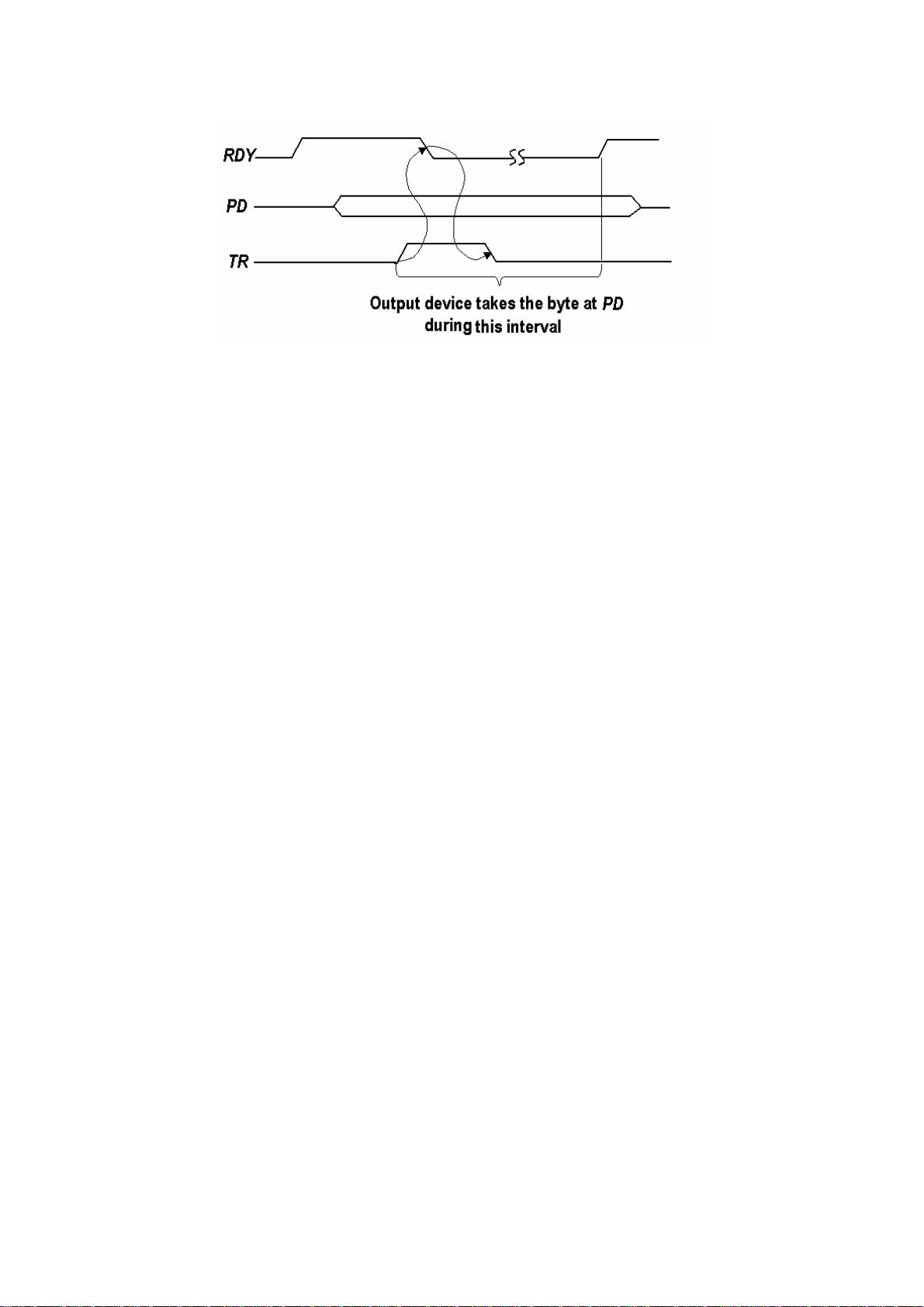
Figure 2 The handshake-timing diagram between POC and the printer
The handshaking process is described as follows: When the printer is ready to receive
a character, it holds RDY=1.The POC must then hold a character at PD (parallel data)
port and produce a pulse at the terminal TR (transfer request). The printer will change
RDY to 0, take the character at PD and hold the RDY at 0 until the character has been
printed (e.g. 5 or 10ms), then set RDY=1 again when it is ready to receive the next
character. (Suppose the printer has only a one character “buffer” register, so that each
character must be printed before the next character is sent).
In order to ease your design work, the further explanations of the POC
operations and some design hints are given as follows:
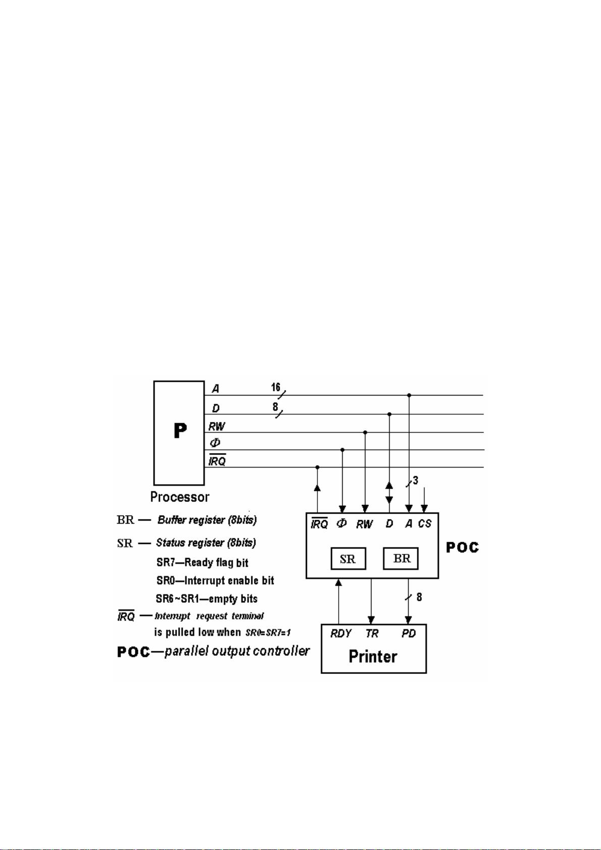
The buffer register BR is used to hold a character that has been sent via the system
bus while that the character is being transferred to the printer. The status register SR is
used for two control functions: SR7serves as a ready flag for system bus transfers to
BR (like the printer RDY signal for transfers from POC to the printer), and SR0 is
used to enable or disable interrupt requests from POC. If SR0=1, then POC will
interrupt when it is ready to receive a character (i.e., when SR7=1). If SR0=0, then
POC will not interrupt. The other bits of SR are not used and empty.
The transfer of a character to POC via the system bus proceeds as follows. POC
indicates that it is ready by setting SR7.The processor reads SR (by executing a
polling or interrupt service routine) and, finding SR7=1, writes a character to BR. The
POC clears SR7 when it loads this character into BR to indicate that another
character should not be sent for the moment. POC then proceeds to transfer the
character in BR to the printer by generating a pulse at TR. The processor, in the
meantime, continues to fetch and execute instructions .If it should happen to read SR,
it will find SR7=0 and hence will not attempt to send another character to the printer.
When the printer is ready to receive another character, POC sets SR7.The transfer
cycle can now repeat.
4
Requirements of the experiment report
The experiment report should be written in English and following items should be
included in it with the same order: ①Title of the experiment; ②Purpose; ③Tasks;
④The overall connection of the simulated printer and POC expressed in the top
module form; ⑤Design description of the simulation input waveforms; ⑥
Simulation results (waveforms record and explanation); ⑦ Conclusions and
Discussions; Appendix (includes a design report, etc.)
Hint for simulation
In order to simulate the POC by computer, a simulated printer must be created in advance by
behavior modeling. It’s circuit and simulation waveforms are shown in Figure 3(a) and (b).For
simplicity, the 8bit parallel data port of the simulated printer is ignored.The circuit of the
simulated printer is by setting a ready signal (RDY) to indicate that it is ready to receive the next
new character from the PD(8bit parallel data port)of the POC. The receiving is started in response
to the leading edge of the TR signal transmitted from the POC, and the RDY is cleared to indicate
that the printer is busy. After some time interval, the RDY is set again, indicating the current
character printing is finished and the printer is ready for next turn. The interval is set to only 5
clock periods by an UP/DOWN counter 74193 (in down counting mode).This is a simplified
modeling of the real printer, it is for the convenience of the simulation waveforms observing
(because the real time interval may be of the order of mini-seconds).The overall connection of the
simulated printer and POC is shown in Figure 3(c).
(a)The internal circuit of the simulated printer module
剩余17页未读,继续阅读
ruijiankun
- 粉丝: 0
- 资源: 10
上传资源 快速赚钱
- 我的内容管理 展开
- 我的资源 快来上传第一个资源
- 我的收益 登录查看自己的收益
- 我的积分 登录查看自己的积分
- 我的C币 登录后查看C币余额
- 我的收藏
- 我的下载
- 下载帮助
安全验证
文档复制为VIP权益,开通VIP直接复制
信息提交成功
评论0