没有合适的资源?快使用搜索试试~ 我知道了~
毫米波雷达天线、毫米波雷达天线罩设计、TI天线罩
需积分: 3 9 下载量 133 浏览量
2023-03-27
15:56:11
上传
评论 1
收藏 2.63MB PDF 举报
温馨提示
试读
22页
毫米波雷达天线、毫米波雷达天线罩设计、TI天线罩
资源推荐
资源详情
资源评论
Application Report
mmWave Radar Radome Design Guide
Chethan Kumar, Habeeb Ur Rahman Mohammed and Greg Peake
ABSTRACT
Radar technology has evolved in last decades from military applications such as missile control, ground
surveillance, air traffic control to numerous automotive and industrial applications such as adaptive cruise
control, park assist, autonomous parking, motion and presence detection, level sensing, people counting and
more. In order for a radar sensor to perform flawlessly in these applications it is critical to ensure that the radome
or housing is designed to minimize electrical and environmental interferences to the radar sensor antenna. This
application report provides an introduction to radome design and highlights key care abouts for designing a
mmWave radome whilst considering the radar sensor performance. It describes a concept of radome design
considerations, along with radome test and qualification. Examples of different radome structures are presented
with supporting design simulations and measurement results.
Table of Contents
1 Introduction and Challenges................................................................................................................................................. 3
2 Radome Design Elements......................................................................................................................................................3
2.1 Understanding Dielectric Constant and Loss tangent on Radome and Antenna Design...................................................3
2.2 Impedance Mismatch at Radome Boundaries................................................................................................................... 3
2.3 Radome Wall Thickness.....................................................................................................................................................5
2.4 Antenna to Radome Distance............................................................................................................................................ 6
3 Typical Radome Material Examples...................................................................................................................................... 7
4 Radome Angle Dependent Error........................................................................................................................................... 7
4.1 Rectangular Radome Angle Dependent Error................................................................................................................... 7
4.2 Spherical Radome Angle Dependent Error........................................................................................................................8
4.3 Effect of the Angle Error in the Application.........................................................................................................................9
5 Radome Design and Simulations........................................................................................................................................10
6 Radome Lab Experiments....................................................................................................................................................16
6.1 Radome Experiment – 1: Flat Plastic Radome................................................................................................................ 16
6.2 PTFE Material Rectangular Radome............................................................................................................................... 17
6.3 PTFE-Based Curved Radome......................................................................................................................................... 18
7 Additional Considerations................................................................................................................................................... 19
7.1 Antenna Calibration..........................................................................................................................................................19
7.2 Radome Near Proximity Considerations.......................................................................................................................... 20
8 Summary............................................................................................................................................................................... 20
9 Acknowledgments................................................................................................................................................................21
10 References.......................................................................................................................................................................... 21
List of Figures
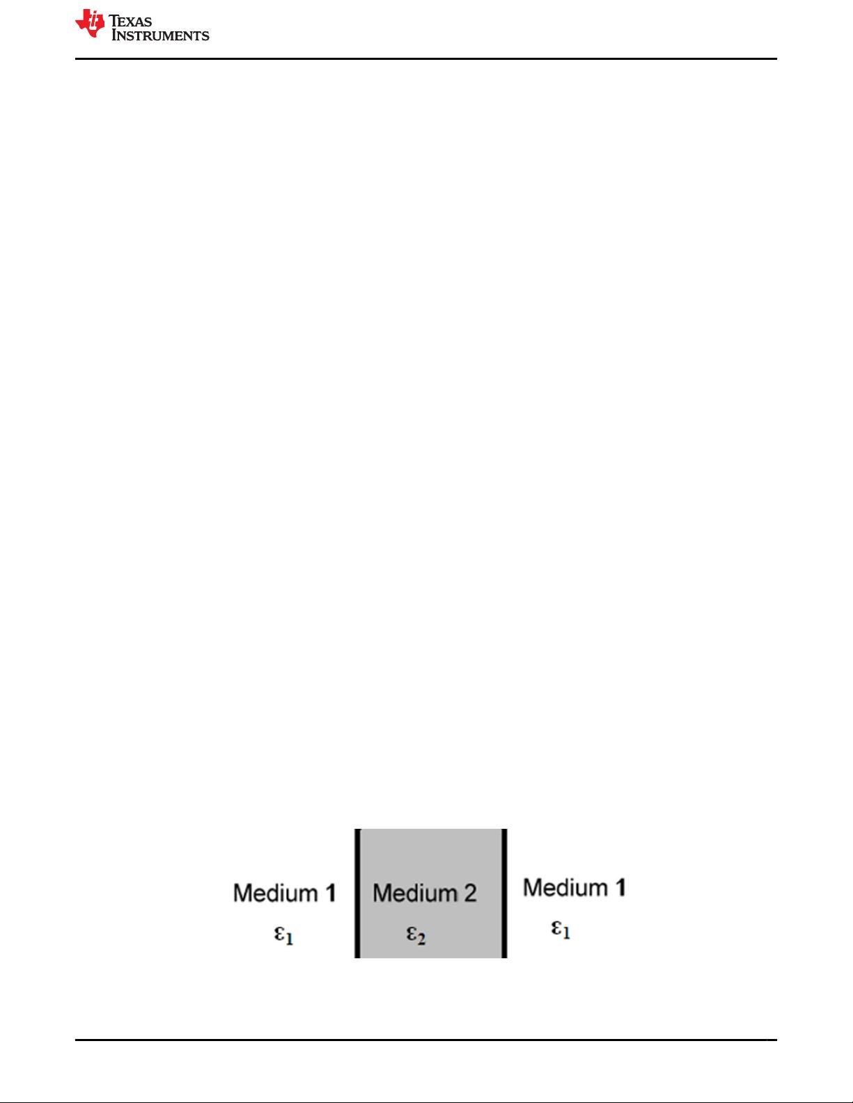
Figure 2-1. Boundary of Mismatch Between Dielectric Mediums................................................................................................ 3
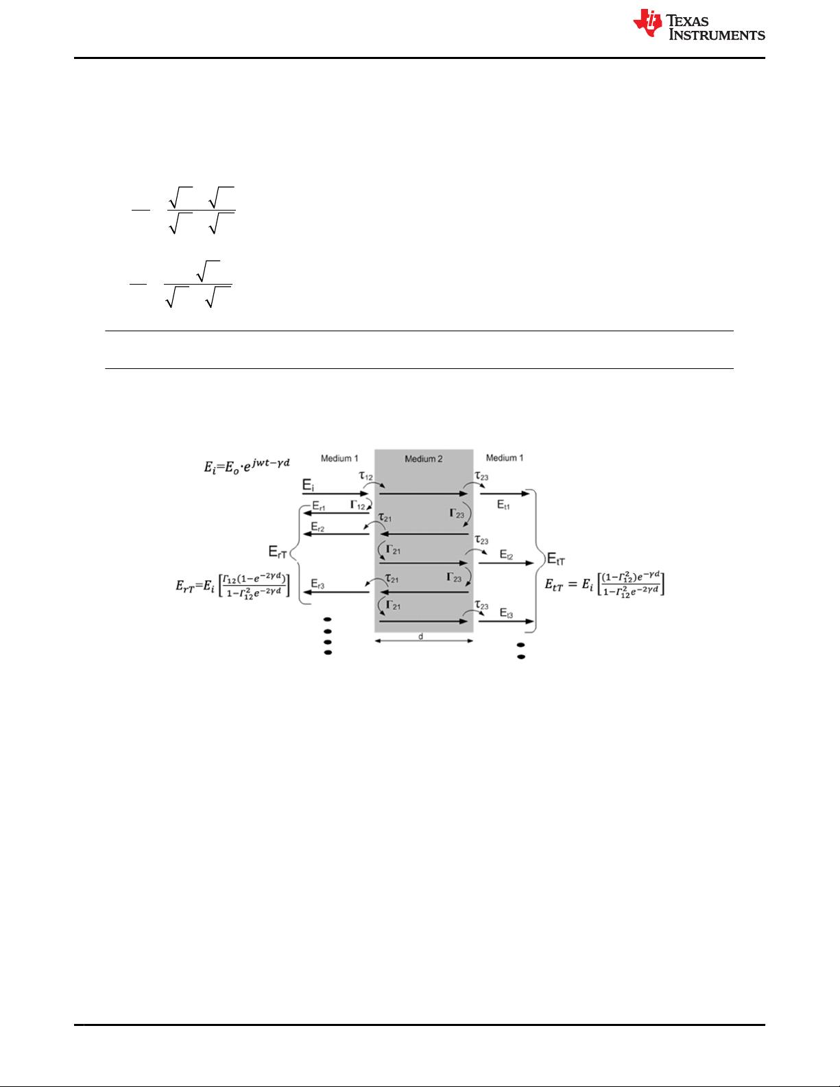
Figure 2-2. Multiple Reflections at Boundaries of Dielectric Mediums ........................................................................................4
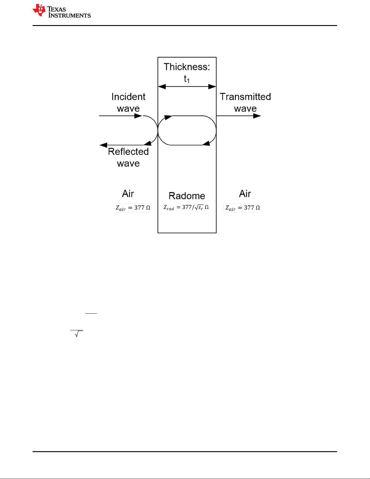
Figure 2-3. Reflections at Radome Boundaries (assumption is that radome has a solid single wall...........................................5
Figure 2-4. Radome Optimal Thickness versus Dielectric for Incident Waves of Different Frequency........................................6
Figure 2-5. Radome Optimal Thickness versus Frequency for Different Dielectrics .................................................................. 6
Figure 4-1. Distance Traveled in Rectangular Radome Wall for Different Grazing Angles..........................................................8
Figure 4-2. Distance Traveled in Spherical Radome Wall for Different Grazing Angles..............................................................8
Figure 4-3. The Effect of Angle Estimation Error With Rectangular Radomes ........................................................................... 9
Figure 4-4. The Effect of Angle Estimation Error With Spherical Radomes.................................................................................9
Figure 5-1. Spherical Radome HFSS Model: 37.44 mm outer radius....................................................................................... 10
Figure 5-2. Spherical Radome HFSS Model: 18.24 mm Outer Radius..................................................................................... 10
www.ti.com Table of Contents
SWRA705 – AUGUST 2021
Submit Document Feedback
mmWave Radar Radome Design Guide 1
Copyright © 2021 Texas Instruments Incorporated
Figure 5-3. Smaller Spherical HFSS Model: Corresponding Dimensions and Placement With Semi-Transparent View of
PCB........................................................................................................................................................................................10
Figure 5-4. Larger Spherical HFSS Model: Corresponding Dimensions and Placement With Semi-Transparent View of
PCB........................................................................................................................................................................................10
Figure 5-5. Radome Radius of Curvature is Based on Antenna Aperture and FoV Requirement.............................................11
Figure 5-6. Radiation Pattern Tx. Azimuth Without Radome..................................................................................................... 11
Figure 5-7. Radiation Pattern Tx Azimuth With Radome Radius 18.24 mm..............................................................................11
Figure 5-8. Radiation Pattern Tx Azimuth With Radome Radius 37.44 mm..............................................................................12
Figure 5-9. Radiation Pattern Tx Azimuth With Radome Radius 32.64 mm..............................................................................12
Figure 5-10. Radiation Pattern Rx Azimuth Without Radome .................................................................................................. 12
Figure 5-11. Radiation Pattern Rx Azimuth With Radome Radius 18.24 mm............................................................................13
Figure 5-12. Radiation Pattern Rx Azimuth With Radome Radius 37.44 mm........................................................................... 13
Figure 5-13. Radiation Pattern Rx Azimuth With Radome Radius 32.64 mm........................................................................... 13
Figure 5-14. Radiation Pattern Tx. Elevation Without Radome................................................................................................. 14
Figure 5-15. Radiation Pattern Tx Elevation With Radome Radius 18.24 mm..........................................................................14
Figure 5-16. Radiation Pattern Tx Elevation With Radome Radius 37.44 mm..........................................................................14
Figure 5-17. Radiation Pattern Tx Elevation With Radome Radius 32.64 mm..........................................................................15
Figure 5-18. Radiation Pattern Rx Elevation Without Radome .................................................................................................15
Figure 5-19. Radiation Pattern Rx Elevation With Radome Radius 18.24 mm......................................................................... 15
Figure 5-20. Radiation Pattern Rx Elevation With Radome Radius 37.44 mm......................................................................... 16
Figure 5-21. Radiation Pattern Rx Elevation With Radome Radius 32.64 mm......................................................................... 16
Figure 6-1. ABS Plastic Rectangular Radome With 2 mm Wall Thickness............................................................................... 16
Figure 6-2. Azimuth Antenna Radiation Pattern for the 2 mm Wall Thickness ABS Plastic Rectangular Radome................... 17
Figure 6-3. Azimuth Antenna Radiation Patterns With no Radome...........................................................................................17
Figure 6-4. PTFE-Based Rectangular Radome With 1.524 mm Wall Thickness ......................................................................17
Figure 6-5. Antenna Radiation Measurement With PTFE Rectangular Radome...................................................................... 18
Figure 6-6. Antenna Radiation Measurement With no Radome ............................................................................................... 18
Figure 6-7. The PTFE Curved Shaped Radome With 1.524 mm Wall Thickness..................................................................... 18
Figure 6-8. Antenna Radiation Pattern Measurement With no Radome .................................................................................. 19
Figure 6-9. Azimuth Angle Estimation Error Measurement With no Radome - With and Without Phase Calibration................19
Figure 6-10. Elevation Antenna Radiation Pattern With the Curved Shape Radome................................................................19
Figure 6-11. Azimuth Angle Estimation Error Measurement With the Curved Shape Radome - With and Without Phase
Calibration..............................................................................................................................................................................19
List of Tables
Table 3-1. Permittivity and Dissipation Factor for Different Radome Materials............................................................................7
Trademarks
Teflon
®
is a registered trademark of Teflon.
All trademarks are the property of their respective owners.
Trademarks www.ti.com
2 mmWave Radar Radome Design Guide SWRA705 – AUGUST 2021
Submit Document Feedback
Copyright © 2021 Texas Instruments Incorporated
1 Introduction and Challenges
A radome (radar dome) is an electromagnetically transparent protective shield that encloses mmWave Radar
sensors and the antenna. It protects the mmWave antenna and electronics from external environment effects
such as rain, sunlight, wind providing structural weatherproof enclosure. The radome minimally attenuates the
electromagnetic signal transmitted or received by the antenna and as such should effectively be transparent to
radio waves.
In some cases, a radome could be constructed as a lens that alters the beam characteristics intentionally. Such
a radome or lens needs to be designed using electro-magnetic simulation tools in conjunction with the antenna
and desired field of view in consideration.
Based on the needs of specific end equipment, radomes can be constructed in several shapes such as planar,
spherical, and geodesic where the shape will have some influence on the radiation pattern or field of view and
maximum achievable distance by radar sensor. The radome material choice, such as fiberglass, PTFE-coated
fabric, and polycarbonate, is generally dependent on the targeted application environmental use.
2 Radome Design Elements
2.1 Understanding Dielectric Constant and Loss tangent on Radome and Antenna Design
In order to understand the electromagnetic wave propagation in a material it is important to know the material
constitutive parameters, such as, permittivity, permeability and conductivity. These constitutive parameters
characterize the EM properties of the material. From these parameters, special care must be taken in selecting
the radome material with optimum relative permittivity (E
r
) or dielectric constant (Dk). (Most radomes are
designed out of a non-magnetic dielectric material such that the relative permeability = 1 and the conductivity =
0.) Signal fade or “loss” occurs either by the reflection of the electromagnetic waves at the boundary of radome
structure or due to multiple reflections within the radome material itself. This is mainly due to the difference in
dielectric constant (Dk) of the radome relative to air. The dielectric constant (Dk) represents the reflective, as well
as the refractive, properties of a material. In general, the electromagnetic signal can be thought of as “slowing
down” as it moves through the radome when compared with air.
Definition of loss tangent: Dielectric loss quantifies a dielectric material's inherent dissipation of electromagnetic
energy. It can be parametrized in terms of either the loss angle δ or the corresponding loss tangent tan δ.
The dielectric constant and loss tangent together specify the transmission efficiency of a radome combined with
an antenna system where both together are ideally measured at the intended operating frequencies. Dielectric
loss quantifies a dielectric material's inherent dissipation of electromagnetic energy. It can be parametrized in
terms of either the loss angle δ or the corresponding loss tangent tan(δ). The lower the dielectric constant and
loss tangent, the smaller the effect of the radome on the antenna performance. Ideally Dk should be close to 1,
since free space Dk is 1. However, it is impractical to use materials that have Dk=1 (basically Styrofoam) since
they are not suitable for other goals of the radome (aesthetics, cost, and environmental robustness). Just to note
that it is not the antenna design that forces Dk>1, but rather the radome material properties and availability.
2.2 Impedance Mismatch at Radome Boundaries
Electromagnetic wave reflections occur at the boundaries of the plane of mismatch. This plane of mismatch
could be considered as boundary of two medium with different dielectric properties, that is, mediums with
different permittivity as shown in Figure 2-1.
Figure 2-1. Boundary of Mismatch Between Dielectric Mediums
www.ti.com Introduction and Challenges
SWRA705 – AUGUST 2021
Submit Document Feedback
mmWave Radar Radome Design Guide 3
Copyright © 2021 Texas Instruments Incorporated
These reflections due to impedance mismatch can be better understood by looking into electromagnetic wave
interaction at the impedance mismatch planes. The interaction of the electromagnetic wave at these planes
leads to the reflection and transmission of waves at the boundary of medium, which is quantized in terms of
reflection coefficient Γ and transmission coefficient
τ
. The reflection coefficient is the ratio of reflected E
r
and
incident
E
i
electric field strength and transmission coefficient is the ratio of transmitted E
t
and incident E
i
electric
field strength as shown in Equation 1 and Equation 2.
Γ = =
−
+
E
E
r
i
ε ε
ε ε
1 2
1 2
(1)
τ
ε
ε ε
= =
•
+
E
E
t
i
2
1
1 2
(2)
Note
(1) and (2) are the reflections at only a single interface boundary.
Essentially, there will be multiple reflections occurring within the radome material and resulting in the
accumulation shown in Figure 2-2. This results in a reflected wave (E
rT
) and transmitted wave (E
tT
) created
from the incident wave (E
ri
).
Figure 2-2. Multiple Reflections at Boundaries of Dielectric Mediums
Radome Design Elements www.ti.com
4 mmWave Radar Radome Design Guide SWRA705 – AUGUST 2021
Submit Document Feedback
Copyright © 2021 Texas Instruments Incorporated
Reflections within the radome can be simplified as shown in Figure 2-3. Free space or air wave impedance is
about 377Ω such that the wave impedance inside the radome is given by 377/√ε
r
Ω. Electromagnetic waves will
be reflected back from such that both the air-radome interface and radome-air interface.
Figure 2-3. Reflections at Radome Boundaries (assumption is that radome has a solid single wall
2.3 Radome Wall Thickness
The wall thickness of the radome plays a key role in arriving at the optimum performance of the mmWave radar
sensor. It is important to make sure that the radome wall thickness is equal to an integer multiple of the radar
wavelength/2 so that the radome becomes “nearly transparent” for the mmWave frequency range intended. The
thickness of radome is given in Equation 3. The wavelength in the radome material becomes shorter versus free
air and is an inverse function of the material's dielectric constant as shown in Equation 4.
t
optimum
=
n*λ
m
2
(3)
λ
m
=
C
f* ε
r
(4)
Where,
• t
optimum
= Optimum thickness of radome wall or target thickness to make the radome transparent.
• n: 1,2,3…
• λ
m
: Wavelength of the material
• C: speed of light
• f: mean carrier frequency used (for example, 62 GHz for a typical 60-64 GHz bandwidth)
• ε
r
: relative permittivity
www.ti.com Radome Design Elements
SWRA705 – AUGUST 2021
Submit Document Feedback
mmWave Radar Radome Design Guide 5
Copyright © 2021 Texas Instruments Incorporated
剩余21页未读,继续阅读
资源评论
毫米波雷达、算法、天线、硬件
- 粉丝: 1
- 资源: 29
上传资源 快速赚钱
- 我的内容管理 展开
- 我的资源 快来上传第一个资源
- 我的收益 登录查看自己的收益
- 我的积分 登录查看自己的积分
- 我的C币 登录后查看C币余额
- 我的收藏
- 我的下载
- 下载帮助
安全验证
文档复制为VIP权益,开通VIP直接复制
信息提交成功