1
0509B–8051–04/04
Section 1
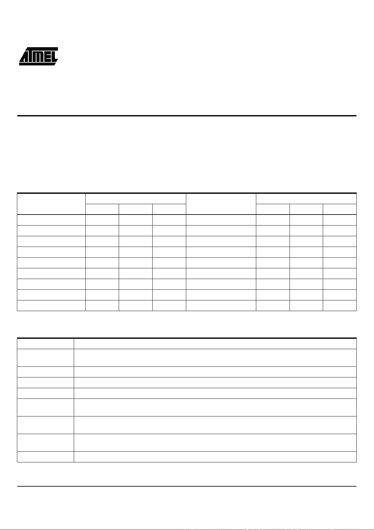
80C51 Microcontrollers Instruction Set
For interrupt response time information, refer to the hardware description chapter.
Note: 1. Operations on SFR byte address 208 or bit addresses 209-215 (that is, the PSW or bits in the PSW) also affect flag settings.
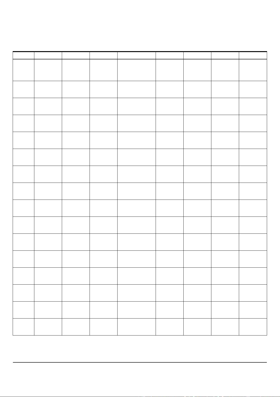
Instructions that Affect Flag Settings
(1)
Instruction Flag Instruction Flag
COVAC COVAC
ADD X X X CLR C O
ADDC X X X CPL C X
SUBB X X X ANL C,bit X
MUL O X ANL C,/bit X
DIV O X ORL C,bit X
DA X ORL C,/bit X
RRC X MOV C,bit X
RLC X CJNE X
SETB C 1
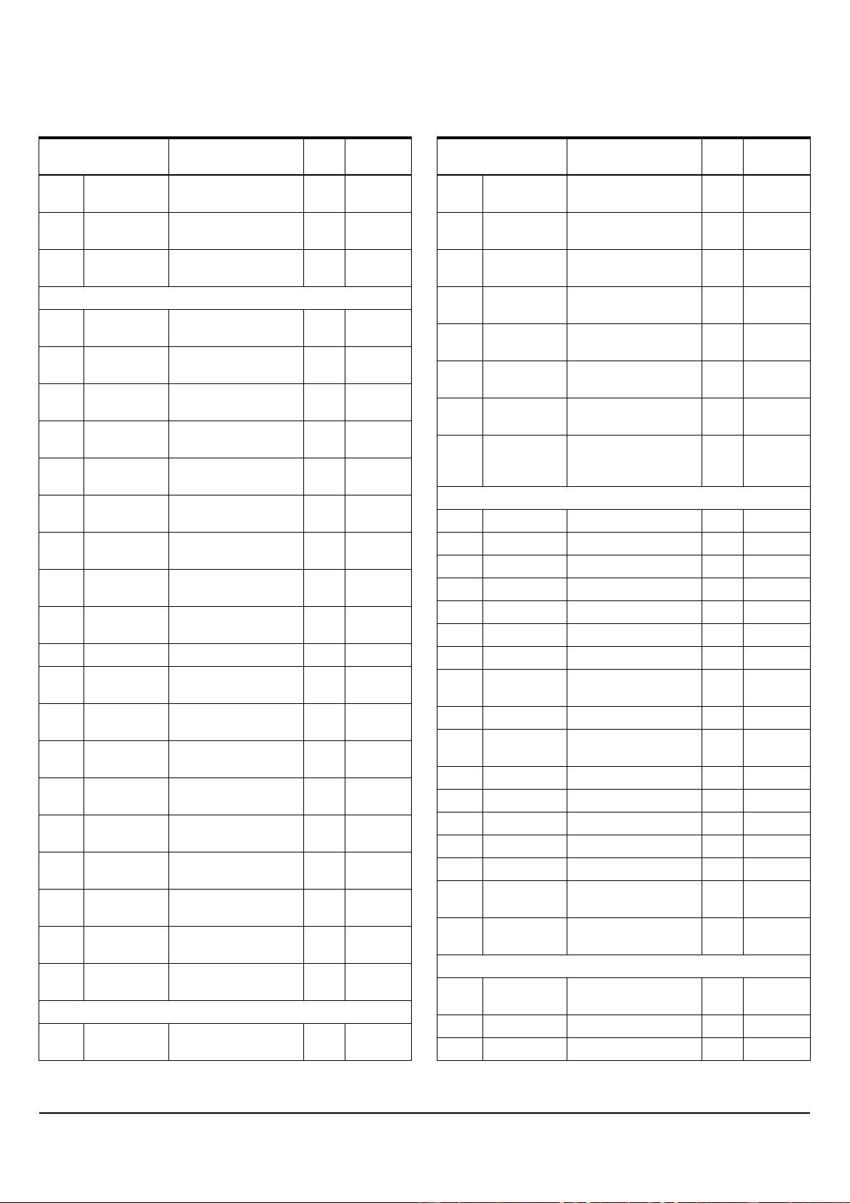
The Instruction Set and Addressing Modes
R
n
Register R7-R0 of the currently selected Register Bank.
direct 8-bit internal data location’s address. This could be an Internal Data RAM location (0-127) or a SFR [i.e., I/O
port, control register, status register, etc. (128-255)].
@R
i
8-bit internal data RAM location (0-255) addressed indirectly through register R1or R0.
#data 8-bit constant included in instruction.
#data 16 16-bit constant included in instruction.
addr 16 16-bit destination address. Used by LCALL and LJMP. A branch can be anywhere within the 64K byte Program
Memory address space.
addr 11 11-bit destination address. Used by ACALL and AJMP. The branch will be within the same 2K byte page of
program memory as the first byte of the following instruction.
rel Signed (two’s complement) 8-bit offset byte. Used by SJMP and all conditional jumps. Range is -128 to +127
bytes relative to first byte of the following instruction.
bit Direct Addressed bit in Internal Data RAM or Special Function Register.