


Mechanical Specifications for
Microcomputers Using REDI
Conduction Cooling
Applied to VITA 46
VITA 48.2
Revision D0.06
10 July 2006
This draft standard is being prepared by the VITA
Standards Organization (VSO) and is unapproved.
Do not specify or claim conformance
to this draft standard.
VSO is the Public Domain Administrator of this draft standard
and guards the contents from change except by sanctioned
meetings of the task group under due process.
VITA Standards Organization
P O Box 19658
Fountain Hills AZ 85269 USA
Ph: 480-837-7486
URL:
http://www.vita.com
Do not specify or claim conformance to this document
Mechanical Specifications for Microcomputers Using REDI, VITA 48.2 (Rev. D0.06) - 1 -
Task Group
At the time this standard was competed, working group membership included:
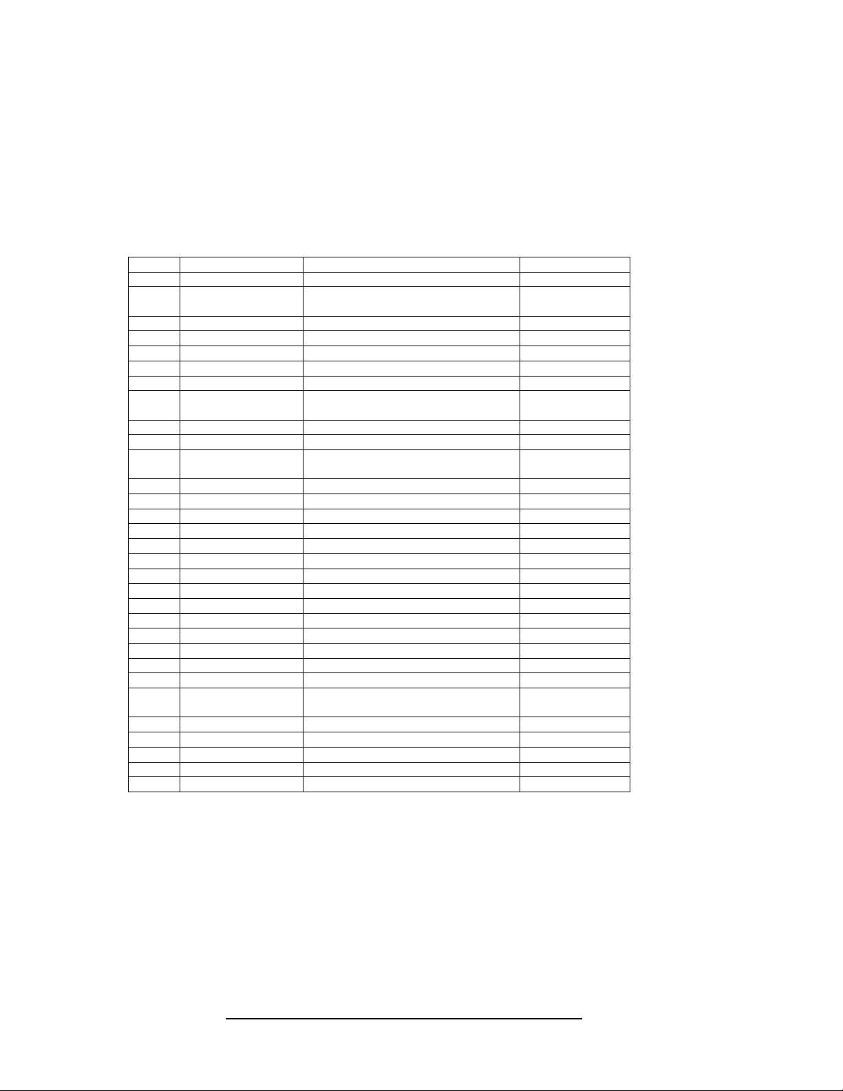
Working Group List VITA 48 Mechanical Requirements
Total Members 31
Name Organization Status
1 Mike Gust Mercury Computer Systems Sponsor
2 Stewart Dewar Curtiss-Wright Controls Embedded
Computing
Sponsor
3 Jim Robles Boeing Inc. Sponsor
4 Michael Benjamin Parker Hannifin Corporation Sponsor
5 Rex Harvey Parker Hannifin Corporation Sponsor
6 Richard Hodges Parker Sponsor
7 Rodger Bird Boeing Inc. Sponsor
8 Ivan Straznicky Curtiss-Wright Controls Embedded
Computing
Sponsor
9 Steve Belvin ISBi Participant
10 Adam Bloch EATON Aerospace Participant
11 Gorky Chin Curtiss-Wright Controls Embedded
Computing
Participant
12 David Compston Radstone Participant
13 Gerard Drewek General Dynamics Participant
14 Doug DuBois L-3 Communications Participant
15 Chris Eckert SBS technologies, Inc. Participant
16 Mark Heslep MITRE Corporation Participant
17 Itzhak Hirshtal Elta Electronic Industries Participant
18 Frank Hom APW Electronic Solutions Participant
19 Andreas Lenkisch Schroff GmbH Participant
20 Charles Linquist Dawn VME Products, Inc. Participant
21 David McCallum Molex Participant
22 Bob Patterson Tyco Electronics Participant
23 Andrew Reddig TEK Microsystems Participant
24 John Rynearson VITA Participant
25 Bob Sullivan Hybricon Corporation Participant
26 Bruce Thomas Curtiss-Wright Controls Embedded
Computing
Participant
27 Michael Thompson Pentair Electronic Packaging Participant
28 Ken Boyette Critia Computer, Inc. Observer
29 Michael Munroe Bustronics Observer
30 Elwood Parsons Standard Consultant Observer
31 Mac Rush Motorola Computer Group Observer
Do not specify or claim conformance to this document
Mechanical Specifications for Microcomputers Using REDI, VITA 48.2 (Rev. D0.06) - 2 -

Comments, Corrections, and/or Additions
Anyone wishing to provide comments, corrections and/or additions to this draft standard please direct
them to the draft editor:
Mike Gust, Draft Editor
Mercury Computer Systems Inc.
199 Riverneck Road
Chelmsford, MA 01824
Ph: 978-967-1332
Fax: 978-256-4778
Email:
mgust@mc.com
The best way to provide corrections and additions is via e-mail.
VSO and Other Standards
Should anyone want information on other standards being developed by VSO, VME Product
Directories, VME Handbooks, or general information on the VME market, please contact the VITA
office at the address or telephone number given on the front cover.
Change Bars
All paragraphs changed in this draft are marked with a change bar on the left side of the paragraph.
Any table entry that was changed will have a bar on the left side of the table.
Do not specify or claim conformance to this document
Mechanical Specifications for Microcomputers Using REDI, VITA 48.2 (Rev. D0.06) - 3 -

Table of Contents
1 Scope..................................................................................................................................................... 7
2 Purpose.................................................................................................................................................. 7
3 Intellectual Property ............................................................................................................................... 7
4 References ............................................................................................................................................ 7
4.1 Terminology................................................................................................................................8
4.1.1 Abbreviations ...................................................................................................................... 8
4.1.2 2 Level Maintenance (2LM) ................................................................................................ 8
4.1.3 Frame vs. Cover.................................................................................................................. 8
4.1.4 Special word usage............................................................................................................. 8
5 Circuit Board .......................................................................................................................................... 9
5.1 Circuit Board Sizes..................................................................................................................... 9
5.2 Conductive elements and guide rails ....................................................................................... 10
5.3 Circuit Board Commonality ...................................................................................................... 10
6 Plug-in unit description ........................................................................................................................ 12
7 Plug-in unit Sizes ................................................................................................................................. 17
7.1 Plug-in unit height..................................................................................................................... 18
7.2 Plug-in unit depth ..................................................................................................................... 18
7.3 Plug-in unit thickness and plug-in unit frame, cover and PCB relationship ............................. 18
7.4 Wedge clamp location.............................................................................................................. 30
7.5 Additional wedge clamp considerations................................................................................... 30
7.6 Keying and guide pin/socket .................................................................................................... 32
7.7 Primary side cover.................................................................................................................... 32
7.8 Secondary side cover............................................................................................................... 33
7.9 Plug-in unit insertion/extraction features.................................................................................. 33
8 Guidance on cooling............................................................................................................................ 33
9 Position of plug-in unit mounted connectors and backplane mounted connectors ............................. 36
9.1 Position of connectors on the plug-in units .............................................................................. 36
9.2 Position of backplane mounted connectors ............................................................................. 36
9.3 Backplane Rigidity.................................................................................................................... 37
9.4 Dimensions............................................................................................................................... 37
10 Sub-rack ............................................................................................................................................ 48
11 Filler panels/slot blockers .................................................................................................................. 55
11.1 Conduction cooled systems.................................................................................................. 55
12 EMC................................................................................................................................................... 55
13 Two Level Maintenance (2LM) considerations.................................................................................. 55
Appendix A.............................................................................................................................................. 56
Tolerance Analysis for ............................................................................................................................ 56
Conduction Cooled ................................................................................................................................. 56
Plug-in Units ........................................................................................................................................... 56
A1. Overview ...................................................................................................................................... 57
A2. Plug-in unit Considerations.......................................................................................................... 57
A3. Connector Considerations ........................................................................................................... 59
A4. Sub-rack considerations .............................................................................................................. 60
A5. Analysis approach........................................................................................................................ 63
A5.1. Worst case tolerance analysis.............................................................................................. 63
A5.2. Root Sum-of-Square (RSS) tolerance analysis.................................................................... 63
A5.3. Monte Carlo analysis ............................................................................................................ 64
A6. Analysis Results – Secondary Side Wedge Clamp ..................................................................... 64
A6.1. Worst case tolerance analysis.............................................................................................. 64
A6.2. RSS tolerance analysis ........................................................................................................ 64
A6.3. Monte Carlo analysis ............................................................................................................ 64
A7. Analysis Results – Primary Side Wedge Clamp.......................................................................... 66
A7.1. Worst case tolerance analysis.............................................................................................. 66
A7.2. RSS tolerance analysis ........................................................................................................ 67
A7.3. Monte Carlo analysis ............................................................................................................ 67
Do not specify or claim conformance to this document
Mechanical Specifications for Microcomputers Using REDI, VITA 48.2 (Rev. D0.06) - 4 -

A8. Wedge clamp side gap considerations........................................................................................ 68
A8.1. Wedge clamp on the secondary side of the plug-in unit .......................................................... 68
A8.1.1. Worst case tolerance analysis.............................................................................................. 69
A8.1.2. RSS tolerance analysis ........................................................................................................ 69
A8.2. Wedge clamp on the primary side of the plug-in unit............................................................... 69
A8.2.1. Worst case tolerance analysis.............................................................................................. 70
A8.2.2. RSS tolerance analysis ........................................................................................................ 70
A9. Thermal expansion/contraction considerations ........................................................................... 70
A10. Summary/conclusion ................................................................................................................ 71
Table of Figures
Figure 1. 3U board size. ..................................................................................................................... 10
Figure 2. 6U board size, component side 1 (primary side) view. .......................................................... 11
Figure 3. General configuration of 3U conduction cooled plug-in units on 0.80 and 0.85 in. centers.13
Figure 4. General configuration of 3U conduction cooled plug-in units on 1.00 in. centers, primary side
wedge clamps. .................................................................................................................... 13
Figure 5. General configuration of 3U conduction cooled plug-in units on 1.00 in. centers, secondary
side wedge clamps.
............................................................................................................. 14
Figure 6. General configuration of 6U conduction cooled plug-in units on 0.80 and 0.85 in. centers... 15
Figure 7. General configuration of a 1.00 in. pitch 6U conduction cooled plug-in unit, primary side
wedge clamps.
.................................................................................................................... 16
Figure 8. General configuration of a 1.00 in. pitch 6U conduction cooled plug-in unit, secondary side
wedge clamps.
.................................................................................................................... 17
Figure 9. Envelope dimensions for a Type 1, 3U, 0.80 in. pitch conduction cooled plug-in unit
assembly.
............................................................................................................................ 20
Figure 10. Envelope dimensions for a Type 1, 3U, 0.85 in. pitch conduction cooled plug-in unit
assembly.
............................................................................................................................ 21
Figure 11. Envelope dimensions for a Type 1, 3U, 1.00 in. pitch conduction cooled plug-in unit
assembly.
............................................................................................................................ 22
Figure 12. Envelope dimensions for a Type 1, 3U, 1.00 in. pitch conduction cooled plug-in unit
assembly.
............................................................................................................................ 23
Figure 13. Envelope dimensions for a Type 1, 6U, 0.80 in. pitch conduction cooled plug-in unit
assembly.
............................................................................................................................ 24
Figure 14. Envelope dimensions for a Type 1, 6U, 0.85 in. pitch conduction cooled plug-in unit
assembly.
............................................................................................................................ 25
Figure 15. Envelope dimensions for a Type 1, 6U, 1.00 in. pitch conduction cooled plug-in unit
assembly.
............................................................................................................................ 26
Figure 16. Envelope dimensions for a Type 1, 6U, 1.00 in. pitch conduction cooled plug-in unit
assembly.
............................................................................................................................ 27
Figure 17. Envelope dimensions for 3U and 6U conduction cooled plug-in unit assemblies showing the
relationship of plug-in unit cover size as a function of plug-in unit pitch.
............................ 28
Figure 18. Plug-in unit frame-to-PCB relationship. Dimensions shown are applicable to both 3U and
6U form factor plug-in units.
................................................................................................ 29
Figure 19. Location of wedge clamp on 0.80 in. pitch plug-in units (3U and 6U) that is compliant with
an IEEE 1101.2 compliant sub-rack interface.
.................................................................... 31
Figure 20. Location of wedge clamp on 0.85 in. pitch plug-in units (3U and 6U) that is compliant with
an IEEE 1101.2 compliant sub-rack interface.
.................................................................... 31
Figure 21. Location of wedge clamp on 1.00 in. pitch plug-in units (3U and 6U) that is compliant with
an IEEE 1101.2 compliant sub-rack interface.
.................................................................... 31
Figure 22. Location of wedge clamp on 1.00 in. pitch plug-in units (3U and 6U) that is compliant with
an IEEE 1101.2 compliant sub-rack interface.
.................................................................... 32
Figure 23. Plug-in unit insertion process and required features in the extraction/insertion lever and
sub-rack.
.............................................................................................................................. 34
Figure 24. Plug-in unit extraction process and required features in the extraction/insertion lever and
sub-rack.
.............................................................................................................................. 35
Figure 25. View of sub-rack showing features required for insertion and extraction............................. 36
Do not specify or claim conformance to this document
Mechanical Specifications for Microcomputers Using REDI, VITA 48.2 (Rev. D0.06) - 5 -


