1
FEATURES
DESCRIPTION
APPLICATIONS
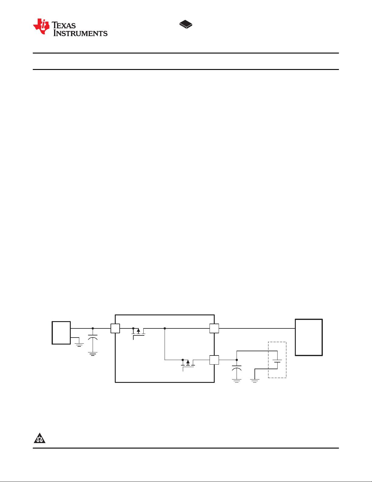
POWER FLOW DIAGRAM
(1)
IN
BAT
OUT
bq24070/1
PACK+
PACK−
System
VDC
GND
AC Adapter
+
Q1
Q2
UDG−04082
40 mΩ
(2)
bq24070
bq24071
www.ti.com
........................................................................................................................................................... SLUS694D – MARCH 2006 – REVISED MAY 2008
SINGLE-CHIP LI-ION CHARGE AND SYSTEM POWER-PATH MANAGEMENT IC
• Small 3,5 mm × 4,5 mm QFN Package
• Designed for Single-Cell Li-Ion- or
The bq24070 and bq24071 are highly integrated
Li-ion linear charger and system power-path
Li-Polymer-Based Portable Applications
management devices targeted at space-limited
• Integrated Dynamic Power-Path Management
portable applications. The bq24070/1 offer DC supply
(DPPM) Feature Allowing the AC Adapter to
(AC adapter) power-path management with
Simultaneously Power the System and Charge
autonomous power-source selection, power FETs
the Battery
and current sensors, high-accuracy current and
• Power Supplement Mode Allows Battery to
voltage regulation, charge status, and charge
termination, in a single monolithic device.
Supplement the AC Input Current
• Autonomous Power Source Selection (AC
The bq24070/1 power the system while
Adapter or BAT)
independently charging the battery. This feature
reduces the charge and discharge cycles on the
• Supports Up to 2 Amps Total Current
battery, allows for proper charge termination and
• Thermal Regulation for Charge Control
allows the system to run with an absent or defective
• Charge Status Outputs for LED or System
battery pack. This feature also allows for the system
Interface Indicates Charge and Fault
to instantaneously turn on from an external power
source in the case of a deeply discharged battery
Conditions
pack. The IC design is focused on supplying
• Reverse Current, Short-Circuit, and Thermal
continuous power to the system when available from
Protection
the AC adapter or battery sources.
• Power Good Status Outputs
• 4.4-V and 6-V Options for System Output
Regulation Voltage
• Smart Phones and PDA
• MP3 Players
• Digital Cameras and Handheld Devices
• Internet Appliances
(1) See Figure 2 and functional block diagram for more detailed feature information.
(2) P-FET back gate body diodes are disconnected to prevent body diode conduction.
1
Please be aware that an important notice concerning availability, standard warranty, and use in critical applications of
Texas Instruments semiconductor products and disclaimers thereto appears at the end of this data sheet.
PRODUCTION DATA information is current as of publication date.
Copyright © 2006 – 2008, Texas Instruments Incorporated
Products conform to specifications per the terms of the Texas
Instruments standard warranty. Production processing does not
necessarily include testing of all parameters.