


Second
Ed
ition
Data
Networks
DIMITRI
BERTSEKAS
Massachusetts Institute
of
Technology
ROBERT
GALLAGER
Massachusetts Institute
of
Technology
PRENTICE
HALL,
Englewood Cliffs, New Jersey 07632
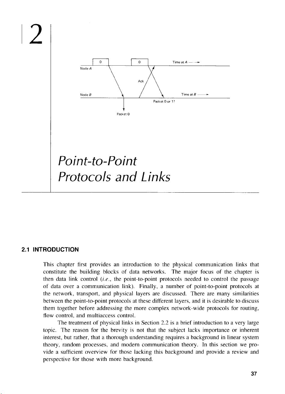
2
Node A
Node B
Packet 0
Point-to-Point
Protocols and
Links
2.1
INTRODUCTION
Time at B ---------
This chapter first provides an introduction to the physical communication links that
constitute the building blocks
of
data networks. The major focus
of
the chapter
is
then data link control (i.e., the point-to-point protocols needed to control the passage
of
data over a communication link). Finally, a number
of
point-to-point protocols at
the network, transport, and physical layers are discussed. There are many similarities
between the point-to-point protocols at these different layers, and
it
is
desirable to discuss
them together before addressing the more complex network-wide protocols for routing,
flow control, and multiaccess control.
The treatment
of
physical links
in
Section 2.2
is
a brief introduction to a very large
topic. The reason for the brevity is not that the subject lacks importance or inherent
interest, but rather, that a thorough understanding requires a background
in
linear system
theory, random processes, and modem communication theory. In this section
we
pro-
vide a sufficient overview for those lacking this background and provide a review and
perspective for those with more background.
37

38
Point-to-Point Protocols and Links Chap. 2
In
dealing with the physical layer
in
Section 2.2,
we
discuss both the actual com-
munication channels used by the network and whatever interface modules are required at
the ends
of
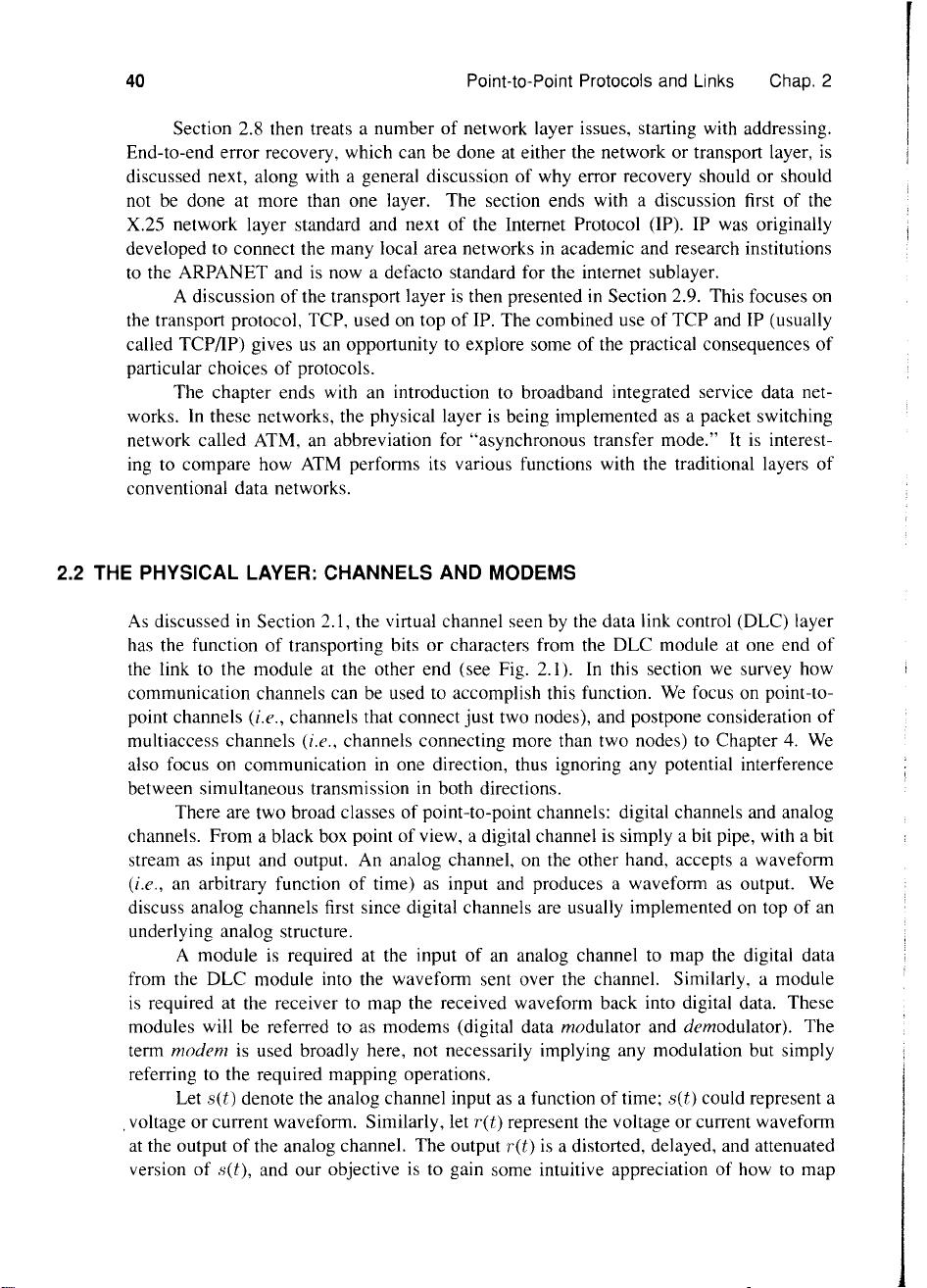
the channels to transmit and receive digital data (see Fig 2.1).
We
refer to
these modules as modems (digital data modulators and demodulators), although in many
cases no modulation or demodulation
is
required.
In
sending data, the modem converts
the incoming binary data into a signal suitable for the channel.
In
receiving, the modem
converts the received signal back into binary data.
To
an extent, the combination
of
mo-
dem, physical link, modem can be ignored; one simply recognizes that the combination
appears to higher layers
as
a virtual bit pipe.
There are several different types
of
virtual bit pipes that might be implemented
by the physical layer. One is the
synchronous bit pipe, where the sending side
of
the
data link control (DLC) module supplies bits to the sending side
of
the modem
at
a
synchronous rate
(i.e., one bit each T seconds for some fixed T). If the DLC module
temporarily has no data to send, it must continue to send dummy bits, called
idle fill,
until it again has data. The receiving modem recovers these bits synchronously (with
delay and occasional errors) and releases the bits, including idle fill, to the corresponding
DLC module.
The
intermittent synchronous bit pipe
is
another form
of
bit pipe
in
which the
sending DLC module supplies bits synchronously to the modem when it has data to
send, but supplies nothing when it has no data. The sending modem sends no signal
during these idle intervals, and the receiving modem detects the idle intervals and releases
nothing to the receiving DLC module. This somewhat complicates the receiving modem,
since it must distinguish between
0,
1,
and idle
in
each time interval, and
it
must also
regain synchronization
at
the end
of
an
idle period.
In
Chapter 4 it will be seen that the
capability to transmit nothing
is
very important for multiaccess channels.
A final form
of
virtual bit pipe is the asynchronous character pipe, where the bits
within a character are sent at a fixed rate, but successive characters can
be
separated by
Packets
Frames
Virtual synchronous unreliable
bit
pipe
Communication
link
Figure 2.1 Data link control (DLC) layer with interfaces
to
adjacent layers.
Sec.
2.1
Introduction
39
variable delays, subject to a given minimum.
As
will be seen
in
the next section, this is
used only when high data rates are not
an
important consideration.
In Sections 2.3 to 2.7
we
treat the DLC layer, which
is
the primary focus
of
this
chapter. For each point-to-point link, there are two DLC peer modules, one module at
each end
of
the link. For traffic
in
a given direction, the sending DLC module receives
packets from the network layer module at that node. The peer DLC modules employ
a distributed algorithm, or protocol, to transfer these packets
to
the receiving DLC and
thence to the network layer module
at
that node. In most cases, the objective is to deliver
the packets in the order
of
arrival, with neither repetitions nor errors. In accomplishing
this task, the DLC modules make use
of
the virtual bit pipe (with errors) provided by
the physical layer.
One major problem in accomplishing the objective above
is
that
of
correcting the
bit errors that occur on the virtual bit pipe. This objective
is
generally accomplished
by a technique called ARQ (automatic
repeat request).
In
this technique, errors are
first detected at the receiving DLC module and then repetitions are requested from the
transmitting DLC module. Both the detection
of
errors and the requests for retransmission
require a certain amount
of
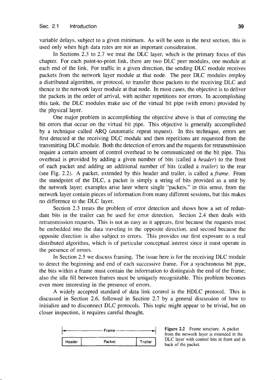
control overhead to be communicated on the bit pipe. This
overhead is provided by adding a given number of bits (called a
header) to the front
of
each packet and adding
an
additional number
of
bits (called a trailer) to the rear
(see Fig. 2.2). A packet, extended by this header and trailer,
is
called a frame. From
the standpoint
of
the DLC, a packet
is
simply a string
of
bits provided
as
a unit by
the network layer; examples arise later where single "packets,"
in
this sense, from the
network layer contain pieces
of
information from many different sessions, but this makes
no difference to the DLC layer.
Section 2.3 treats the problem
of
error detection and shows how a set
of
redun-
dant bits
in
the trailer can be used for error detection. Section 2.4 then deals with
retransmission requests. This
is
not
as
easy as it appears, first because the requests must
be
embedded into the data traveling
in
the opposite direction, and second because the
opposite direction
is
also subject to errors. This provides our first exposure to a real
distributed algorithm, which
is
of
particular conceptual interest since it must operate in
the presence
of
errors.
In
Section 2.5 we discuss framing. The issue here
is
for the receiving DLC module
to detect the beginning and end
of
each successive frame. For a synchronous bit pipe,
the bits within a frame must contain the information to distinguish the end
of
the frame;
also the idle
fill
between frames must
be
uniquely recognizable. This problem becomes
even more interesting in the presence
of
errors.
A widely accepted standard
of
data link control
is
the HDLC protocol. This
is
discussed in Section 2.6, followed
in
Section 2.7 by a general discussion
of
how to
initialize and to disconnect DLC protocols. This topic might appear to be trivial, but
on
closer inspection, it requires careful thought.
1
•.
------
Frame
---------<·~I
IHeader
Packet
Trailer
I
Figure 2.2 Frame structure. A packet
from the network layer
is
extended
in
the
DLC layer with control bits
in
front and in
back of the packet.
40
Point-to-Point Protocols and Links Chap. 2
Section 2.8 then treats a number
of
network layer issues, starting with addressing.
End-to-end error recovery, which can be done at either the network or transport layer,
is
discussed next, along with a general discussion of why error recovery should or should
not be done at more than one layer. The section ends with a discussion first
of
the
X.25 network layer standard and next
of
the Internet Protocol (IP). IP was original1y
developed to connect the many local area networks in academic and research institutions
to
the ARPANET and
is
now a defacto standard for the internet sublayer.
A discussion
of
the transport layer
is
then presented in Section 2.9. This focuses on
the transport protocol, TCP, used on top
of
IP. The combined use
of
TCP and
IP
(usual1y
cal1ed TCP/IP) gives us an opportunity to explore some
of
the practical consequences
of
particular choices
of
protocols.
The chapter ends with an introduction to broadband integrated service data net-
works.
In
these networks, the physical layer
is
being implemented
as
a packet switching
network called ATM, an abbreviation for "asynchronous transfer mode." It
is
interest-
ing to compare how
ATM
performs its various functions with the traditional layers
of
conventional data networks.
2.2 THE PHYSICAL LAYER: CHANNELS AND MODEMS
As
discussed in Section 2.1, the virtual channel seen by the data link control (DLC) layer
has the function
of
transporting bits or characters from the DLC module at one end
of
the link to the module
at
the other end (see Fig. 2.1). In this section we survey how
communication channels can be used to accomplish this function.
We
focus on point-to-
point channels
(i.e., channels that connect just two nodes), and postpone consideration
of
multiaccess channels (i.e., channels connecting more than two nodes) to Chapter 4.
We
also focus on communication
in
one direction, thus ignoring any potential interference
between simultaneous transmission in both directions.
There are two broad classes
of
point-to-point channels: digital channels and analog
channels. From a black box point of view, a digital channel is simply a bit pipe, with a bit
stream
as
input and output. An analog channel, on the other hand, accepts a waveform
(i.e., an arbitrary function
of
time)
as
input and produces a waveform
as
output.
We
discuss analog channels first since digital channels are usually implemented on top
of
an
underlying analog structure.
A module
is
required at the input
of
an analog channel to map the digital data
from the DLC module into the waveform sent over the channel. Similarly, a module
is
required at the receiver to map the received waveform back into digital data. These
modules
wil1
be referred to
as
modems (digital data modulator and demodulator). The
term
modem
is
used broadly here, not necessarily implying any modulation but simply
referring to the required mapping operations.
Let
set) denote the analog channel input
as
a function
of
time; set) could represent a
.voltage or current waveform. Similarly, let
ret)
represent the voltage or current waveform
at
the output
of
the analog channel. The output
ret)
is
a distorted, delayed, and attenuated
version
of
set), and our objective
is
to gain some intuitive appreciation of how
to
map


- 1
- 2
前往页