没有合适的资源?快使用搜索试试~ 我知道了~
X-Ray_Imaging_and_Computed_Tomography
需积分: 9 9 下载量 98 浏览量
2012-01-09
00:25:05
上传
评论
收藏 15.1MB PDF 举报
温馨提示
试读
56页
X-Ray_Imaging_and_Computed_Tomography
资源推荐
资源详情
资源评论
1
X-Ray Imaging
and
Computed Tomography
1.1. GENERAL PRINCIPLES OF IMAGING WITH X-RAYS
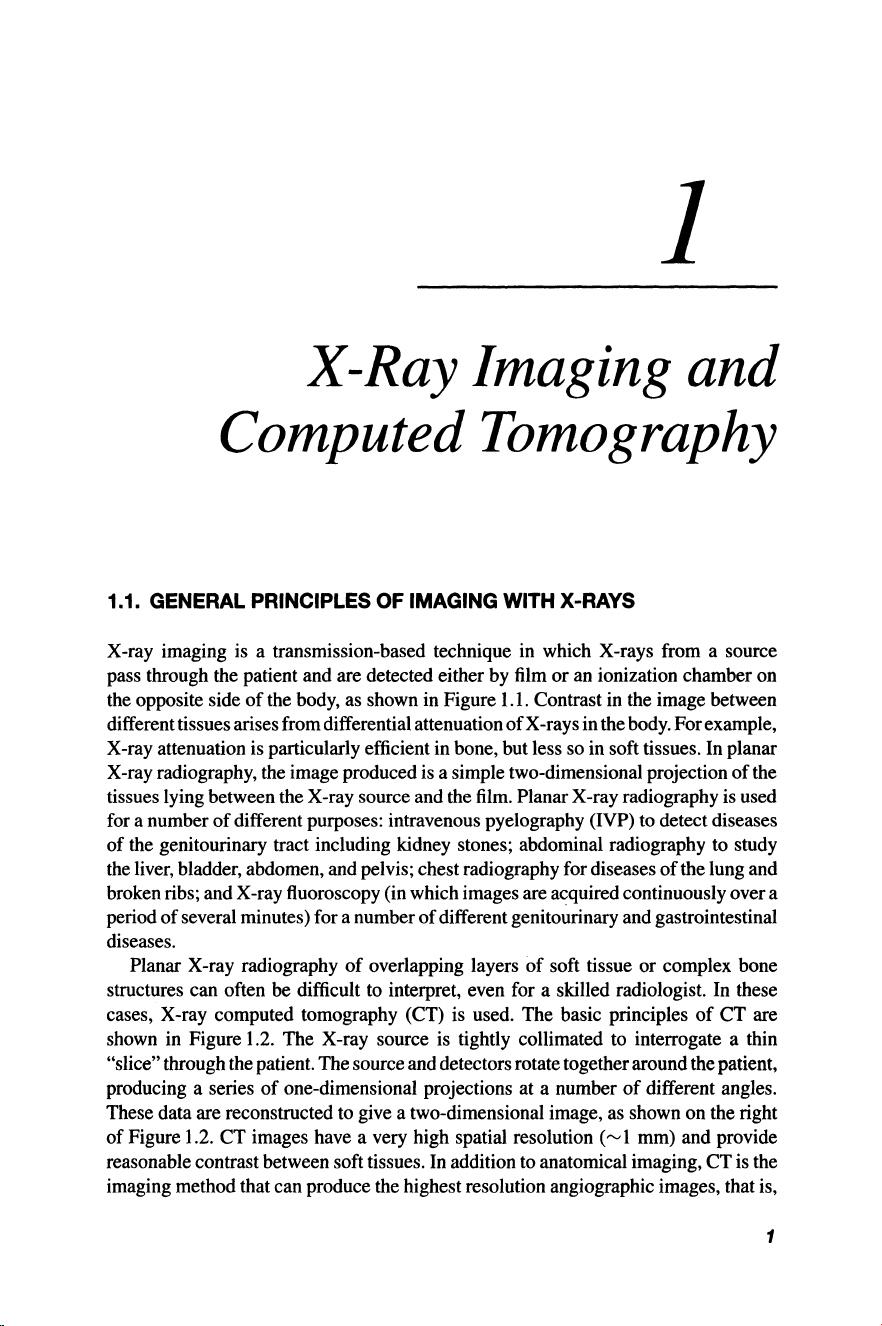
X-ray imaging is a transmission-based technique in which X-rays from a source
pass through the patient and are detected either by film or an ionization chamber on
the opposite side
of
the body, as shown in Figure 1.1. Contrast in the image between
different tissues arises from differential attenuation
of
X-rays in the body. For example,
X-ray attenuation is particularly efficient in bone, but less so in soft tissues. In planar
X-ray radiography, the image produced is a simple two-dimensional projection of the
tissues lying between the X-ray source and the film. Planar X-ray radiography is used
for a number
of
different purposes: intravenous pyelography (IVP) to detect diseases
of the genitourinary tract including kidney stones; abdominal radiography to study
the liver, bladder, abdomen, and pelvis; chest radiography for diseases
of
the lung and
broken ribs; and X-ray fluoroscopy (in which images are acquired continuously over a
period of several minutes) for a number
of
different genitourinary and gastrointestinal
diseases.
Planar X-ray radiography
of
overlapping layers of soft tissue or complex bone
structures can often be difficult to interpret, even for a skilled radiologist. In these
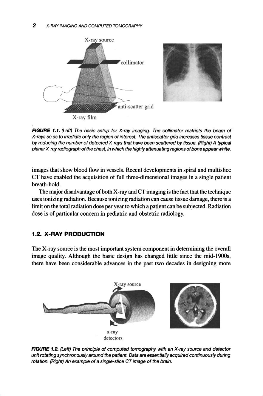
cases, X-ray computed tomography (CT) is used. The basic principles
of
CT are
shown in Figure 1.2. The X-ray source is tightly collimated to interrogate a thin
"slice" through the patient. The source and detectors rotate togetheraround the patient,
producing a series
of
one-dimensional projections at a number
of
different angles.
These data are reconstructed to give a two-dimensional image, as shown on the right
of Figure 1.2. CT images have a very high spatial resolution
("v
1 mm) and provide
reasonable contrast between soft tissues. In addition to anatomical imaging, CT is the
imaging method that can produce the highest resolution angiographic images, that is,
1
2 X-RAYIMAGINGAND COMPUTED
TOMOGRAPHY
collimator
X-ray film
FIGURE
1.1. (Left) The basic setup for X-ray imaging. The collimator restricts the beam
of
X-rays so as to irradiate only the region
of
interest. The antiscatter
grid
increases tissue contrast
by reducing the number
of
detected X-rays that have been scattered by tissue. (Right) A typical
planarX-ray radiograph
of
the chest, in which the highlyattenuatingregions
of
boneappearwhite.
images that show blood flowin vessels. Recent developments in spiral and multislice
CT have enabled the acquisition of full three-dimensional images in a single patient
breath-hold.
The major disadvantage of both X-ray and CT imaging is the fact that the technique
uses ionizing radiation. Because ionizing radiation can cause tissue damage, there is a
limit on the total radiation dose per year to which a patient can be subjected. Radiation
dose is of particular concern in pediatric and obstetric radiology.
1.2. X-RAY PRODUCTION
The X-ray source is the most important system component in determining the overall
image quality. Although the basic design has changed little since the mid-1900s,
there have been considerable advances in the past two decades in designing more
x-ray
detectors
FIGURE
1.2. (Left) The principle
of
computed tomography with an X-ray source and detector
unit rotating synchronously around the patient. Data
are essentially acquiredcontinuously during
rotation. (Right) An example
of
a single-slice CT image
of
the brain.
1.2.
X-RAY
PRODUCTION
3
efficient X-ray sources , which are capable
of
delivering the much higher output levels
necessary for techniques such as CT and X-ray fluoroscopy.
1.2.1. The X-Ray Source
The basic components
of
the X-ray source, also referred to as the X-ray tube, used
for clinical diagnoses are shown in Figure 1.3. The production
of
X-rays involves
accelerating a beam
of
electrons to strike the surface
of
a metal target. The X-ray
tube has two electrodes, a negatively charged cathode, which acts as the electron
source, and a positively charged anode, which contains the metal target. A potential
difference of between 15and 150 kV is applied between the cathode and the anode; the
exact value depends upon the particular application. This potential difference is in the
form of a rectified alternating voltage, which is characterized by its maximum value,
the kilovolts peak (kVp). The maximum value
of
the voltage is also referred to as the
accelerating voltage. The cathode consists
of
a filament of tungsten wire ("'-'200
J.Lm
in diameter) coiled to form a spiral
"'2
mm in diameter and less than 1 cm in height.
An electric current from a power source passes through the cathode, causing it to heat
up. When the cathode temperature reaches "'22OO°C the thermal energy absorbed
by the tungsten atoms allows a small number of electrons to move away from the
metallic surface, a process termed thermionic emission . A dynamic equilibrium is set
glass/metal envelope
X-rays
FIGURE1.3. A schematic
of
an X-ray source used for clinical imaging.
4 X-RAY IMAGING AND COMPUTED TOMOGRAPHY
-ve
electrons
~
- - - ,
...
. I -
.....
--
- - - -
.
----
:
---:-
- -
--
-
-
-
-
----
~
i
Ir-
~
- -
----
--
- -
-
" ,
~
- -
-
-:
,
I I
~----
~
X-rays
--.
.-
effective focal
spot size
/
, ,
, ,
, ,
, ,
, ,
, ,
..
~
'
coverage
f
FIGURE 1.4. (rop) Anegatively charged focusing
cup
within the X-ray cathode producesa tightly
focused beam
of
electrons
and
increases the electron flux striking the tungsten anode. (Bottom)
The effect
of
the anode bevel angle () on the effective focal
spot
size f and the X-ray coverage.
up, with electrons having sufficient energy to escape from the surface of the cathode,
but also being attracted back to the metal surface.
The large positive voltage applied to the anode causes these free electrons created
at the cathode surface to accelerate toward the anode. The spatial distribution of these
electrons striking the anode correlates directly with the geometry
of
the X-ray beam
that enters the patient. Since the spatial resolution of the image is determined by the
effective focal spot size, shown in Figure
lA
, the cathode is designed to produce
a tight, uniform beam of electrons.
In order to achieve this, a negatively charged
focusing cup is placed around the cathode to reduce divergence of the electron beam.
The larger the negative potential applied to the cup, the narrower is the electron beam.
If
an extremely large potential (---2kV) is applied, then the flux
of
electrons can be
switched off completely. This switching process forms the basis for pulsing the X-ray
source on and off for applications such as CT, covered in Section
1.10.
At the anode, X-rays are produced as the accelerated electrons penetrate a few
tens of micrometers into the metal target and lose their kinetic energy. This energy is
converted into X-rays by mechanisms covered in detail in Section 1.2.3. The anode
must be made of a metal with a high melting point, good thermal conductivity, and
low vapor pressure (to enable a vacuum
of
less than 10-
7
bar to be established within
1.2.X-RAY
PRODUCTION
5
the vessel). The higher the atomic number of the metal in the target, the higher is the
efficiency of X-ray production, or radiation yield. The most commonly used anode.
metal is tungsten, which has a high atomic number of 74, a high melting point of
3370°C, and the lowest vapor pressure,
10-
7
bar at 2250°C,
of
all metals. Elements
with higher atomic number, such as platinum (78) and gold (79), have much lower
melting points and so are not practical as anode materials. For mammography, in
which the X-rays required are of much lower energy, the anode usually consists of
molybdenum rather than tungsten. Even with the high radiation yield of tungsten,
most of the energy absorbed by the anode is converted into heat, with only
"J
1%
of
the energy being converted into X-rays. If pure tungsten is used, then cracks form in
the metal, and so a tungsten-rhenium alloy with between 2% and 10% rhenium has
been developed to overcome this problem. The target is about 700
/Lm thick and is
mounted on the same thickness of pure tungsten. The main body of the anode is made
from an alloy
of
molybdenum, titanium, and zirconium and is shaped into a disk.
As shown in Figure 1.4, the anode is beveled, typically at an angle
of
5-20°,
in
order to produce a small effective focal spot size, which in tum reduces the geometric
"unsharpness" of the X-ray image (Section 1.6.2). The relationship between the actual
focal spot size
F and the effective focal spot size f is given by
f = F
sine
(1.1)
where
eis the bevel angle. Values of the effective focal spot size range from 0.3 mm
for mammography to between 0.6 and 1.2 mm for planar radiography. In practice,
most X-ray tubes contain two cathode filaments of different sizes to give the option
of using a smaller or larger effective focal spot size. The effective focal spot size can
also be controlled by increasing or decreasing the value of the negative charge applied
to the focusing cup
of
the cathode.
The bevel angle
ealso affects the coverage
of
the X-ray beam, as shown in Fig-
ure 1.4. The approximate value
of
the coverage is given by
coverage
= 2(source-to-patient distance) tan ()
(1.2)
All
of
the components
of
the X-ray system are contained within an evacuated vessel.
In the past, this was constructed from glass, but more recently glass has been replaced
by a combination
of
metal and ceramic. The major disadvantage with glass is that
vapor deposits, from both the cathode filament and the anode target, form on the inner
surface
of
the vessel, causing electrical arcing and reducing the life span of the tube.
The evacuated vessel is surrounded by oil for both cooling and electrical isolation.
The whole assembly is surrounded by a lead shield with a glass window, through
which the X-ray beam is emitted.
1.2.2. X-Ray Tube Current, Tube Output, and Beam Intensity
The tube current(rnA)
of
an X-ray source is defined in terms of the number
of
electrons
per second that travel from the tungsten cathode filament to the anode. Typical values
剩余55页未读,继续阅读
资源评论
h13512
- 粉丝: 0
- 资源: 1
上传资源 快速赚钱
- 我的内容管理 展开
- 我的资源 快来上传第一个资源
- 我的收益 登录查看自己的收益
- 我的积分 登录查看自己的积分
- 我的C币 登录后查看C币余额
- 我的收藏
- 我的下载
- 下载帮助
安全验证
文档复制为VIP权益,开通VIP直接复制
信息提交成功