没有合适的资源?快使用搜索试试~ 我知道了~
资源推荐
资源详情
资源评论
Simulink Basics Tutorial
Starting Simulink
Basic Elements
Building a System
Running Simulations
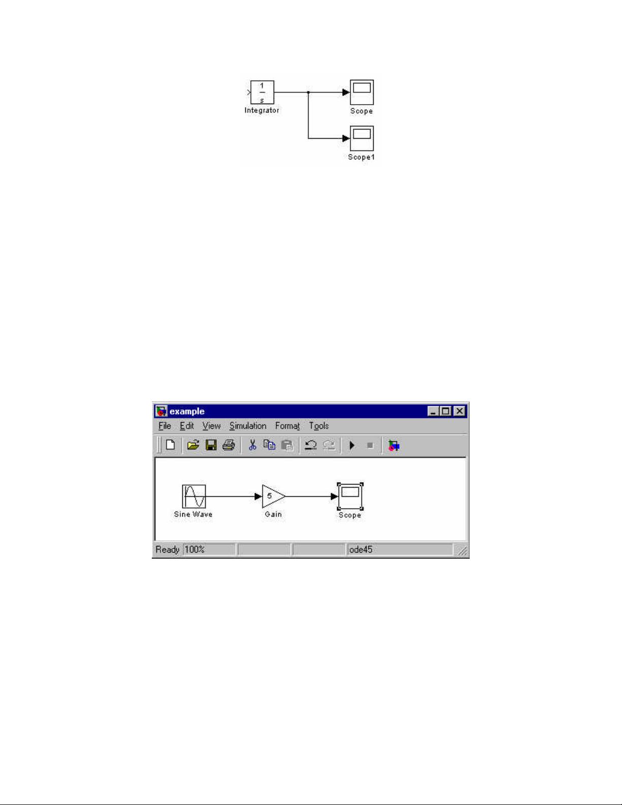
Simulink is a graphical extension to MATLAB for the modeling and simulation of systems. In
Simulink, systems are drawn on screen as block diagrams. Many elements of block diagrams are
available (such as transfer functions, summing junctions, etc.), as well as virtual input devices
(such as function generators) and output devices (such as oscilloscopes). Simulink is integrated
with MATLAB and data can be easily transferred between the programs. In this tutorial, we will
introduce the basics of using Simulink to model and simulate a system.
Simulink is supported on Unix, Macintosh, and Windows environments, and it is included in the
student version of MATLAB for personal computers. For more information on Simulink, contact
the MathWorks.
The idea behind these tutorials is that you can view them in one window while
running Simulink in another window. Do not confuse the windows, icons, and
menus in the tutorials for your actual Simulink windows. Most images in these
tutorials are not live - they simply display what you should see in your own
Simulink windows. All Simulink operations should be done in your Simulink
windows.
Starting Simulink
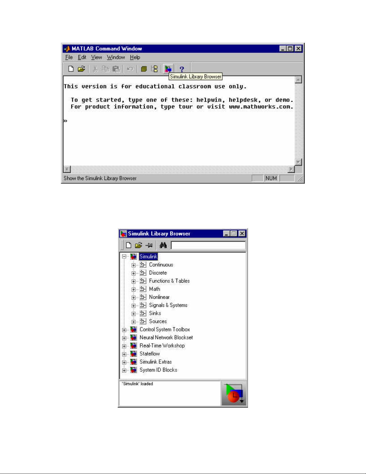
Simulink is started from the MATLAB command prompt by entering the following command:
simulink
Alternatively, you can click on the "Simulink Library Browser" button at the top of the MATLAB
command window as shown below:
The Simulink Library Browser window should now appear on the screen. Most of the blocks
needed for modeling basic systems can be found in the subfolders of the main "Simulink" folder
(opened by clicking on the "+" in front of "Simulink"). Once the "Simulink" folder has been
opened, the Library Browser window should look like:
Basic Elements
There are two major classes of elements in Simulink: blocks and lines. Blocks are used to
generate, modify, combine, output, and display signals. Lines are used to transfer signals from
one block to another.
Blocks
The subfolders underneath the "Simulink" folder indicate the general classes of blocks available
for us to use:
• Continuous: Linear, continuous-time system elements (integrators, transfer functions,
state-space models, etc.)
• Discrete: Linear, discrete-time system elements (integrators, transfer functions, state-
space models, etc.)
• Functions & Tables: User-defined functions and tables for interpolating function values
• Math: Mathematical operators (sum, gain, dot product, etc.)
• Nonlinear: Nonlinear operators (coulomb/viscous friction, switches, relays, etc.)
• Signals & Systems: Blocks for controlling/monitoring signal(s) and for creating
subsystems
• Sinks: Used to output or display signals (displays, scopes, graphs, etc.)
• Sources: Used to generate various signals (step, ramp, sinusoidal, etc.)
Blocks have zero to several input terminals and zero to several output terminals. Unused input
terminals are indicated by a small open triangle. Unused output terminals are indicated by a
small triangular point. The block shown below has an unused input terminal on the left and an
unused output terminal on the right.
Lines
Lines transmit signals in the direction indicated by the arrow. Lines must always transmit signals
from the output terminal of one block to the input terminal of another block. One exception to
this is that a line can tap off of another line. This sends the original signal to each of two (or
more) destination blocks, as shown below:
Lines can never inject a signal into another line; lines must be combined through the use of a
block such as a summing junction.
A signal can be either a scalar signal or a vector signal. For Single-Input, Single-Output systems,
scalar signals are generally used. For Multi-Input, Multi-Output systems, vector signals are often
used, consisting of two or more scalar signals. The lines used to transmit scalar and vector
signals are identical. The type of signal carried by a line is determined by the blocks on either
end of the line.
Building a System
To demonstrate how a system is represented using Simulink, we will build the block diagram for
a simple model consisting of a sinusoidal input multiplied by a constant gain, which is shown
below:
This model will consist of three blocks: Sine Wave, Gain, and Scope. The Sine Wave is a
Source Block from which a sinusoidal input signal originates. This signal is transferred through
a line in the direction indicated by the arrow to the Gain Math Block. The Gain block modifies
its input signal (multiplies it by a constant value) and outputs a new signal through a line to the
Scope block. The Scope is a Sink Block used to display a signal (much like an oscilloscope).
We begin building our system by bringing up a new model window in which to create the block
diagram. This is done by clicking on the "New Model" button in the toolbar of the Simulink
Library Browser (looks like a blank page).
Building the system model is then accomplished through a series of steps:
1. The necessary blocks are gathered from the Library Browser and placed in the model
window.
2. The parameters of the blocks are then modified to correspond with the system we are
modelling.
3. Finally, the blocks are connected with lines to complete the model.
Each of these steps will be explained in detail using our example system. Once a system is built,
simulations are run to analyze its behavior.
Gathering Blocks
Each of the blocks we will use in our example model will be taken from the Simulink Library
Browser. To place the Sine Wave block into the model window, follow these steps:
1. Click on the "+" in front of "Sources" (this is a subfolder beneath the "Simulink" folder)
to display the various source blocks available for us to use.
2. Scroll down until you see the "Sine Wave" block. Clicking on this will display a short
explanation of what that block does in the space below the folder list:
3. To insert a Sine Wave block into your model window, click on it in the Library Browser
and drag the block into your workspace.
The same method can be used to place the Gain and Scope blocks in the model window. The
剩余25页未读,继续阅读
资源评论
Jasonchen_auto
- 粉丝: 0
- 资源: 4
上传资源 快速赚钱
- 我的内容管理 展开
- 我的资源 快来上传第一个资源
- 我的收益 登录查看自己的收益
- 我的积分 登录查看自己的积分
- 我的C币 登录后查看C币余额
- 我的收藏
- 我的下载
- 下载帮助
安全验证
文档复制为VIP权益,开通VIP直接复制
信息提交成功