没有合适的资源?快使用搜索试试~ 我知道了~
Railway Track Irregularity Measuring by GNSS INS Integration.pdf
需积分: 3 1 下载量 195 浏览量
2020-04-07
10:13:56
上传
评论
收藏 1.29MB PDF 举报
温馨提示
试读
11页
写的非常好,对学习惯导很有用!
资源推荐
资源详情
资源评论
Railway Track Irregularity Measuring by GNSS/
INS Integration
QIJIN CHEN, XIAOJI NIU, QUAN ZHANG, and YAHAO CHENG
GNSS Research Center, Wuhan University
Received November 2013; Revised August 2014
ABSTRACT: Railway track irregularity measuring is a task of fundamental importance to guarantee operating
safety and arrange proper maintenance, particularly for the high-speed lines. Conventional measuring methods
cannot satisfy the requirements of accuracy and time-efficiency simultaneously. A GNSS/INS integrated technique
is proposed based on the fact that railway track irregularity detection is essentially an issue of relative surveying. Key
technologies of the integration algorithm aiming at track irregularity measuring are proposed to improve the
performance of the GNSS/INS system. Results show that the proposed method can fulfill 1 mm relative accuracy
in identifying track irregularities in the kinematic surveying mode, which means this method can satisfy the
accuracy requirement for a high-speed line and is ten times faster than the conventional method based on total
station. Copyright # 2015 Institute of Navigation
INTRODUCTION
The railway track condition tends to deteriorate
due to some external factors, such as frequent
passage of heavy trains and deformation of the track
bed. These factors make the railway track drift away
from its designed geometry thus result in track
irregularity [1]. Track irregularity, i.e., track
deformation, is one of the most important factors
that cause safety problems and further track
deterioration [2]. So detecting and fixing the track
irregularity is a task of fundamental importance to
guarantee high operating safety, especially for the
high-speed lines.
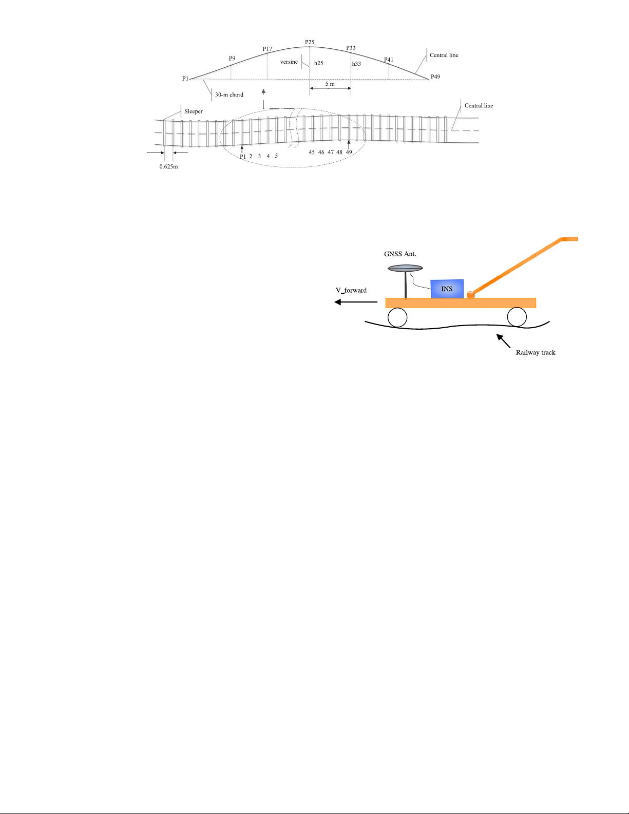
The requirement of track smoothness for the high-
speed line is quite demanding, since even track
deformations with small magnitude (e.g., 2 mm/5 m
for 30-m chord [3]) would lead to considerable
dynamic vehicle response forces under high speed
operation. To detect such small deformations, the
track position should be determined with sub-
millimeter accuracy. In addition, time slots (i.e.,
skylight time) permitted for railway surveying for
the existing line are limited due to high traffic
volumes. Thus flexible surveying systems are
required yielding accurate data within a short time.
Nowadays, railway track irregularities are
primarily measured dynamically by the special track
inspection locomotive, which can be operated at high
speed but does not satisfy the accuracy requirement
for track correction. Lightweight track trolleys
combined with high-precision total station are widely
deployed as a supplement of the dynamic inspection.
The well-known products of the high-precision track
surveying trolley are Amberg GRP1000 by Amberg
Technologies and Trimble GEDO CE. They have
been widely deployed in China for railway cons-
truction and are officially recommended to survey
the unloaded track geometry for track correction
following the dynamic inspection. These types of
track trolleys equipped with motorized total station
claim to measure the absolute deviation of the
railway track from its designed geometry with the
accuracy of 1 millimeter in the stop-and-go mode.
This method has two shortcomings: a) not fast
enough, e.g., we can only survey 150-m of track per
hour using this method; b) surveying accuracy is
determinedly affected by the condition of the railway
construction control network, which is not well
maintained in China for the existing line due to the
huge maintenance cost.
It can be summarized that the conventional
methods cann ot satisfy the requirements of accuracy
and time-efficiency simultaneously. So we propose
to use a GNSS/INS technique to meet these two
requirements.
In previous work, the inertial technique has
been widely utilized for railway track surveying and
track condition monitoring. Inertial sensors, e.g.,
NAVIGATION: Journal of The Institute of Navigation
Vol. 62, No. 1, Spring 2015
Printed in the U.S.A.
83
accelerometers and gyroscopes, are usually equipped
in the railway track surveying equipment to detect
the track irregularity and assess the track condition
by sensing the acceleration and angular rate change
of the corresponding platform. Typically, the inertial
sensors are mounted on the rigid structures of the
train, such as the axle-box, bogie, and car-body to
detect the vertical and lateral track irregularities
[4–11]. The accelerations are first converted to
displacement by double integration; then the track
irregularities are detected with the displacement.
But in this case, the solutions suffer from two issues:
a) the inertial sensor drift is difficult to compensate
for; b) the double integration of sensor noise and
bias causes uncontrolled error in the resulting
displacement, so band-pass filters have to be applied,
which may harm the real motion signal when the
equipment moves at low speed along the track.
The GNSS/INS integrated technique can over-
come the two shortcomings mentioned above by
fusing the GNSS update information and the inertial
outputs in a well-designed Kalman filter. But few
attempts have been made to use GNSS/INS to
detect the track irregularity in the previous work:
Lück discussed the design of track measurement
system based on INS-GPS and integration technique
[12, 13]. This system is designed for the dynamic
inspection locomotive and experimental results from
the laboratory test vehicle have been presented.
Applanix Corp. in partnership with Plasser proposed
a track surveying solution based on a GPS/INS
technique called POS/TG system [14]. POS TG is
also a position and orientation system designed
for a dynam ic inspection locomotive, whose accuracy
for 10 meter mid-chord offset measurement is
claimed to be 1mm (RMS). But we have little
knowledge on the inner technology and algorithm
of POS/TG.
Our research differs from the previous work in
the fact that the proposed method would combine
advantages of the dynamic method and the
lightweight track trolley based on total station.
The GNSS/INS integrated system is mounted on a
lightweight track trolley rather than a locomotive
to realize kinematic surveying and improve time
efficiency. The measurement then would be
accurate enough for track correction/adjustment in
the railway construction and maintenance project.
Challenges for using the GNSS/INS integrated
system to realize sub-millimeter positioning ac-
curacy in this application lie in the fact that the
lightweight track trolley can only move at low speed
compared to the dynamic inspection locomotive,
thus the maneuver experienced by GNSS/INS is
very weak. In this case, the accuracy of the GNSS/
INS system tends to diverge due to the poor
signal-to-noise ratio of the gyro and accelerometer
outputs.
METHODOLOGY
Track Irregularity and Assessment
Track geometry can be regarded as a three-
dimensional curve, which is described in terms of
track curvature, alignment, elevation (cant), and
gauge as functions of distance along the track [5].
Track irregularity refers to the deviation of railway
track from its designed geometry and smoothness,
usually expressed in two separate layouts for
horizontal and vertical. Five typical track irre-
gularities are defined: alignment irregularity,
vertical irregularity, cant, i.e., cross level or super-
elevation, twist, and gauge deviation. Alignment
and vertical irregularity refer to the dev iation of
consecutive measuring points of the rail in the lateral
and vertical direction, respectively, expressed as
excursions from the reference line, i.e., the mean
horizontal and vertical position [15]. Cant, i.e.,
super-elevation, is the difference betwe en the
elevations of the two rails in a curved section, which
is arranged to compensate for part of the lateral
accelerations. Cant irregularity refers to the
difference of the real cant from the nominal value.
Twist refers to the algebraic difference between two
cross levels taken at a defined distance apart, usually
expressed as a gradient between the two points of
measurement [15]. Gauge irregularity refers to the
deviation of the gauge measurement from their
nominal value. In this paper, the alignment and cant
irregularity will be evaluated as examples to
demonstrate the measuring accuracy. The mea-
surement method for vertical irregularity is similar
to that for alignment, and twist can be computed
from consecutive measurements of cant, so these will
not be discussed in detail.
Since rail can be regarded as a three-dimensional
curve, then track irregularities should be expressed
as the relative deviation from their nominal
smoothness. Thus railway track irregularity
detection is inherently an issue of spatial-relative
measurement of the track position and angles. In
other word, once the track position and orientation
are determined, the 3-D track geometry can be
reconstructed based on which track irregularities
could be identified.
The differential versine, illustrated in Figure 1, is
recommended by the China Ministry of Railway as a
standard method of identifying shortwave alignment
and vertical irregularities and evaluating track
smoothness [3]. As shown in Figure 1, the differential
versines for a 30-m chord are consecutively computed
by subtracting two versines 5 meter apart, for
example p25 and p33, by applying equation (1).
Δh ¼ h
25S
h
33S
ðÞh
25D
h
33D
ðÞ
jj
≤ 2mm (1)
where, h
25D
, h
33D
refer to the nominal/designed
versine at p25 and p33, which would be zero for the
84 Navigation Spring 2015
straight line section and constant for the curved
section. h
25S
, h
33S
are the corresponding real
versines computed based on the track position
determination, respectively. The tolerance of the
differential versines Δh for the shortwave track
irregularities, i.e., 30-m chord, is 2 millimeters as
shown in equati on (1). This tolerance is quite
demanding, and implies that a 0.6 mm one- σ error
is required for translating the corresponding
tolerance on a one-dimensional 98.8% interval to
standard deviation for a single point position
determination.
GNSS/INS Measuring Principle
The inertial navigation system (INS) is well
known to be capable of providing position and
attitude measurements with extremely high relati ve
accuracy in a short time. The GNSS/INS inte grated
system can take advantage of GNSS position and
velocity measurement as update information to
compensate the error accumulation of INS, so as to
provide continuous high-precision solutions. For the
railway track irregularity measuring, if the wheels
of the track trolley without suspension can keep
continuous contact with the railway track, then the
3-D track geometry can be uniquely determined by
the position and attitude sequences provided by the
GNSS/INS system as shown in Figure 2. The track
trolley structure is designed rigidly without
suspension, thus the GNSS/INS position and
attitude variations can strictly reflect the variation
of the track smoothness, i.e., track irregularity. For
example, the roll angle reflects the difference
between the elevations of the two rails, according to
which the cant deviation can be detected. Similarly,
the pitch and heading angle reflect the vertical and
alignment variations of the track to some extent. In
this case, the spatial-relative property of the track
irregularity is converted to the time-relative
property through the moving trolley determined by
the time series of position and attitude provided by
the GNSS/INS system. With the GNSS/INS
smoothed position and attitude, we can reconstruct
the 3-D track geometry in the computer software,
based on which the track parameters can be
calculated and track irregularities can be identified.
Figure 3 illustrates the track irregularity measuring
principle of the track trolley based on the GNSS/INS
integrated system.
GNSS/INS Algorithm Description
In this section we will discuss the main point of
the GNSS/INS algorithm, including the Kalman
filter design, the aided method for the accuracy
improvement. Since the radius of curvature of the
high speed railway track is usually large and when
the track trolley runs on the railway at low speed
(i.e., < 10 m/s), the maneuver experienced by the
GNSS/INS system is very weak. In this case, the
accuracy of the GNSS/INS solutions tends to diverge
due to poor signal-to-noise ratio of the gyro and
accelerometers outputs, especially for the heading
angle measurement. To improve the accuracy of
GNSS/INS solution, non-holonomic constraints
(NHC) and smoothing algorithm are implemented
in the GNSS/INS integration algorithm, i.e., Kalman
filter.
Fig. 2–Illustration of the railway track trolley based on the GNSS/
INS system. The trolley is designed rigidly without suspension and
the wheels can keep continuous contact with the rails.
Fig. 1–Differential vesine method of identifying the shortwave (30-chord) irregularity for the
slab track (refer to [3]). The supporting points, e.g., sleepers of the rails are consecutively
arranged with 0.625 meter intervals, and differential versines are obtained by subtracting
two versines 5 meters apart.
85Chen et al.: Railway Track Irregularity by GNSS/INSVol. 62, No.1
剩余10页未读,继续阅读
资源评论
Stone_89217
- 粉丝: 5
- 资源: 9
上传资源 快速赚钱
- 我的内容管理 展开
- 我的资源 快来上传第一个资源
- 我的收益 登录查看自己的收益
- 我的积分 登录查看自己的积分
- 我的C币 登录后查看C币余额
- 我的收藏
- 我的下载
- 下载帮助
安全验证
文档复制为VIP权益,开通VIP直接复制
信息提交成功