没有合适的资源?快使用搜索试试~ 我知道了~
klomp2014.pdf
需积分: 0 0 下载量 93 浏览量
2023-12-18
22:11:46
上传
评论
收藏 1.25MB PDF 举报
温馨提示
试读
17页
klomp2014.pdf
资源推荐
资源详情
资源评论
Vehicle System Dynamics, 2014
Vol. 52, Supplement, 172–188, http://dx.doi.org/10.1080/00423114.2014.887737
Longitudinal velocity and road slope estimation in hybrid
electric vehicles employing early detection of
excessive wheel slip
Matthijs Klomp
a∗
, Yunlong Gao
b
and Fredrik Bruzelius
c
a
Vehicle Dynamics & Controls, e-AAM Driveline Systems, Trollhättan, Sweden;
b
Clean Energy
Automotive Engineering Center, Tongji University, Shanghai, People’s Republic of China;
c
Department of Applied Mechanics, Chalmers University of Technology, Gothenburg, Sweden
(Received 1 November 2013; accepted 21 January 2014)
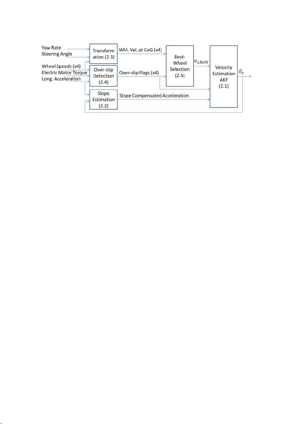
Vehicle speed is one of the important quantities in vehicle dynamics control. Estimation of the slope
angle is in turn a necessity for correct dead reckoning from vehicle acceleration. In the present work,
estimation of vehicle speed is applied to a hybrid vehicle with an electric motor on the rear axle and
a combustion engine on the front axle. The wheel torque information, provided by electric motor,
is used to early detect excessive wheel slip and improve the accuracy of the estimate. A best-wheel
selection approach is applied as the observation variable of a Kalman filter which reduces the influence
of slipping wheels as well as reducing the computational effort. The performance of the proposed
algorithm is illustrated on a test data recorded at a winter test ground with excellent results, even for
extreme conditions such as when all four wheels are spinning.
Keywords: velocity estimation; Kalman filter; wheel torque; best-wheel speed; slope estimation
1. Introduction
Accurate knowledge of the vehicles longitudinal velocity is essential, for example, wheel slip
control and the slope angle are important for real-life fuel economy optimisation and improved
traction control. The task of velocity estimation is challenging when driving all four wheels
and particularly in slippery conditions.
Direct measurement of the longitudinal velocity, as opposed to estimation, is too expensive
and/or impractical for vehicle applications. Therefore, the longitudinal velocity needs to be
estimated from the wheel speed sensors, accelerometers, wheel torque information as well as
other sensors.
These aforementioned sensor sources each have limitations; the wheel speeds become unre-
lated to the vehicle velocity during excessive wheel slip and time integration of the longitudinal
acceleration accumulates sensor bias causing the estimation to drift. Another source of error
is the gravitational component acting in the direction of the road slope contaminating the
acceleration measurement. Hence, estimation of the road slope angle is necessary.
∗
© 2014 Taylor & Francis
Vehicle System Dynamics 173
In order to circumvent the shortcomings of each individual measurement method, it is
necessary to employ sensor fusion.Vehicles with the electric drive system have a more accurate
information of the wheel torque compared with conventionally propelled vehicles. This paper
explores how this improved accuracy can be used to improve the estimation of the longitudinal
velocity.
As mentioned, vehicle speed is one of the important quantities in vehicle dynamics control
and estimation of it has consequently drawn substantial attention in both academic research
as well as in the industry. This fact is confirmed by the amount of published work in the field.
Previously reported approaches range from relaying on auxiliary sensors such as microphones
in [1] to optical sensors as in [2]. However, the most common approach in the literature is
based on estimation using primarily the wheel speed sensors. It is typical to combine these with
accelerometers and inertial measurement unit systems in general and other available sensors
in modern vehicles. Simple heuristic approaches of selecting the best candidate, i.e. with the
smallest wheel slip, can be found in for example.[3,4] These heuristic methods have obvious
advantages and are often popular in the automotive industry due to their simplicity and are
easy to implement. Improvement of the performance by introducing weighted dead reckoning
from accelerometers can be found in [5–7,13]. Incorporation of models and additional sensor
information can be found in for example.[8,9] This further improves the performance of the
estimator, but to the cost of structural complexity, computational burden as well as robustness
to model or sensor errors.
In this work a similar approach as in [10] is taken, namely using simple kinematic models
in combinations with wheel speed sensors and conventional linear Kalman filers in ordinary
working conditions and using dead reckoning of accelerometers for extreme conditions such as
four excessively spinning wheels. The present work extends the work in [10] with an enhanced
algorithm to more rapidly detecting excessive wheel slip by utilising the force information
from the hybrid electric propulsion system. This rapid detection of excessive wheel slip is
essential to minimise the initial estimation off-set when starting the dead reckoning. A strategy
of using only one best-wheel strategy in the Kalman filer further improves robustness of
the estimation.
This paper is organised as follows. The algorithm is developed in Section 2, and Section 3
introduces the test vehicle. Then the test results analysis is explained in Section 4. Finally, the
conclusions are drawn in Section 5.
2. Algorithm design
The estimator used in this paper is based on the standard linear quadratic estimation filter,
known as the Kalman filter. The prediction of the velocity is made by integration of the
slope-compensated longitudinal acceleration and the measurement update is made using the
best-wheel measurement.
As mentioned in the introduction, the accuracy of this Kalman filter could be improved in two
aspects. One is to find excessive wheel slip in time, the other is the best-wheel speed selection.
Hence, the algorithm in this paper is designed based on these principles. As shown in Figure 1,
this algorithm is composed of five parts. Apart from the Kalman filter for velocity estimation,
the other parts, such as wheel velocity transformation, slope estimation (an additional Kalman
filter), wheel speed selection and excessive slip criteria are other key components in the
overall algorithm.
The general discrete system Kalman filter function consists of two parts; a prediction step
using knowledge about the system behaviour and the inputs to the system and a measurement
174 M. Klomp et al.
Figure 1. Algorithm overview with corresponding section numbers in parenthesis.
update, fusing the prediction with measurements:
ˆx
k|k−1
=
k−1
ˆx
k−1|k−1
+
k−1
u
k
P
k|k−1
=
k|k−1
P
k−1|k−1
T
k|k−1
+ Q
k|k−1
K
k
= P
k|k−1
H
T
k
(H
k
P
k|k−1
H
T
k
+ R
k|k−1
)
−1
ˆx
k|k
=ˆx
k|k−1
+ K
k
(z
k
− H
k
ˆx
k|k−1
)
P
k|k
= (I − K
k
H
k
)P
k|k−1
,
(1)
where ˆx
k|k
is the post measurement update estimation states vector at the discrete time-step k,
ˆx
k|k−1
is the pre-estimation (prediction) of the states at step k and u is the inputs vector and z
is the observation variables (measurements) vector. Moreover, P, Q and R are, respectively,
the estimation error, system error and measurement error covariance matrices. Finally, H
k
is
the observation matrix, K
k
is the Kalman filter gain matrix and and are, respectively, the
system matrix and input matrices.
2.1. Velocity estimation
For the velocity estimation Kalman filter (index v) we choose
ˆx
v
=ˆv
x
, u
v
=˙v
x
, z
v
= v
x,BstW
,(2)
where ˆv
x
is the estimated longitudinal velocity, ˙v
x
is the slope-compensated longitudinal accel-
eration (Section 2.2) and v
x,BstW
is the measured velocity based on the selected best-wheel
speed (Section 2.5). Furthermore, we identify that
v
= 1,
v
= τ , H
v
= 1, (3)
where τ is the sample time of the filter. Furthermore, we choose in this work
Q
v
= 1, R
v
= 200 (4)
to estimate the velocity. These gains are tuning variables and need to be calibrated depending
on the application. Note that this Kalman filter is a scalar, thus greatly simplifying the necessary
computations compared with the use of all four wheels.
A key point in the present work is that the Kalman filter gain matrix K is controlled directly
based on rapid detection of excessive slip. When excessive slip of the best wheel is detected
(Section 2.4), the control gain matrix K can be set to zero implying dead reckoning of the
longitudinal acceleration. In the case of no excessive slip of the best wheel, K is updated as
in a typical Kalman filter.
Vehicle System Dynamics 175
Figure 2. Vehicle on sloped road.
2.2. Slope estimation
In general, the measurement of accelerometer is composed of both the acceleration of
movement and the gravity acceleration along the road slope as well as the lateral velocity
component.
As partly shown in Figure 2, the measurement of accelerometer can be written as
a
x
=˙v
x
+ v
y
˙
ψ + g sin α, (5)
where a
x
is the accelerometer measurement, ˙v
x
is the slope compensated longitudinal accel-
eration, g is the gravity acceleration and α is the road slope angle. Furthermore, v
y
˙
ψ is the
product of the lateral velocity, v
y
, and the yaw rate,
˙
ψ. In this work, the lateral velocity is
assumed to be negligible.
Choosing v
x
and sin α as state variables, a
x
as the input variable and ˆv
x
as observation
variable we have that
x =
v
x
sin α
T
, u = a
x
, z =ˆv
x
, (6)
where v
x
and ˆv
x
are the vehicle velocity and its estimation result, respectively.
The state equation can then be written as
˙x =
0 −g
00
x +
1
0
u, (7)
Then, discretise the state function and substitute
α
=
1 −τ g
01
,
α
=
1
0
, H
α
=
10
, (8)
into Equation (1) to estimate the road slope. The prediction and measurement covariance
matrices are chosen as
Q
α
=
10 0
0 0.1
, R
α
= 200. (9)
The observation variable of slope estimation algorithm is the output of velocity estimation,
and the result of slope estimation is used to fix the accelerometer measurement. Then these two
algorithms are combined together. However, when there is excessive wheel slip simultaneously
on all four wheels on a sloped road, neither the wheel speeds nor the acceleration is reliable
in this context. The velocity and slope estimation will be ruined at that time.
剩余16页未读,继续阅读
资源评论
HelloZZZA
- 粉丝: 0
- 资源: 1
上传资源 快速赚钱
- 我的内容管理 展开
- 我的资源 快来上传第一个资源
- 我的收益 登录查看自己的收益
- 我的积分 登录查看自己的积分
- 我的C币 登录后查看C币余额
- 我的收藏
- 我的下载
- 下载帮助
最新资源
- juhua-p8YYy-v0e13a7b5(1).apk
- Neo4j资源:Neo4j.rb的性能测试相关程序
- 排序算法之堆排序算法:用C++语言实现堆排序算法
- 基于Springboot的房屋租赁系统(源代码+论文+说明文档+PPT)-计算机专业精品毕业设计和课程设计
- leidian.py
- 直接插入排序算法:C语言实现直接插入排序算法
- 基于Springboot的大学生就业招聘系统(源代码+论文+说明文档+PPT)-计算机专业精品毕业设计和课程设计
- 基于Vue的H5结婚请帖前端设计源码
- saxaxasxasx
- 基于SSM++jsp的实验室耗材管理系统(源代码+论文+说明文档+PPT)-计算机专业精品毕业设计和课程设计
资源上传下载、课程学习等过程中有任何疑问或建议,欢迎提出宝贵意见哦~我们会及时处理!
点击此处反馈
安全验证
文档复制为VIP权益,开通VIP直接复制
信息提交成功