没有合适的资源?快使用搜索试试~ 我知道了~
TB6600HG PWM 斩波型单芯片双极正弦微步步进马达驱动器
需积分: 0 2 下载量 153 浏览量
2023-05-16
16:33:07
上传
评论
收藏 1.12MB PDF 举报
温馨提示
试读
35页
**特点** 单芯片双极正弦微步步进马达驱动器 Ron (上+下) = 0.4Ω (typ.) 正向和反向旋转控制可用 可选相驱动(1/1, 1/2, 1/4, 1/8, 和 1/16 步) 输出耐压:Vcc = 50 V 输出电流: IOUT = 5.0 A (绝对最大额定值, 峰值) IOUT = 4.5 A (工作范围,最大值) 封装:HZIP25-P-1.00F 内置输入下拉电阻:100 kΩ (typ.), (仅 TQ 端子:70 kΩ(typ.)) 输出监控器引脚(ALERT): IALERT 最大值= 1 mA 输出监控器引脚(MO): IMO 最大值= 1 mA 配备有复位与使能引脚 待机功能 单电源 内置热关机(TSD)电路 内置欠电压锁定(UVLO)电路 内置过流检测(ISD)电路
资源推荐
资源详情
资源评论
TB6600HG
2016-06-10
1
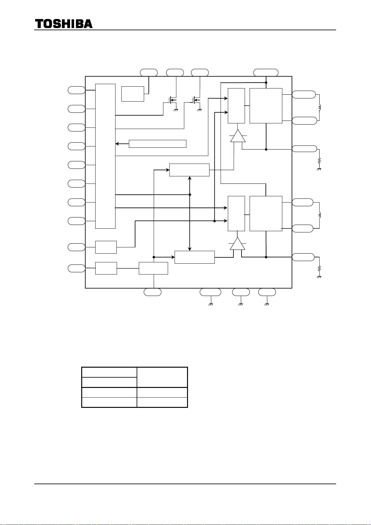
TOSHIBA BiCD Integrated Circuit Silicon Monolithic
TB6600HG
PWM Chopper-Type bipolar
Stepping Motor Driver IC
The TB6600HG is a PWM chopper-type single-chip bipolar sinusoidal
micro-step stepping motor driver.
Forward and reverse rotation control is available with 2-phase,
1-2-phase, W1-2-phase, 2W1-2-phase, and 4W1-2-phase excitation
modes. 东芝代理、大量现货:QQ 990123167 13610068393
2-phase bipolar-type stepping motor can be driven by only clock signal
with low vibration and high efficiency.
Features
• Single-chip bipolar sinusoidal micro-step stepping motor driver
• Ron (upper + lower) = 0.4 Ω (typ.)
• Forward and reverse rotation control available
• Selectable phase drive (1/1, 1/2, 1/4, 1/8, and 1/16 step)
• Output withstand voltage: Vcc = 50 V
• Output current: I
OUT
= 5.0 A (absolute maximum ratings, peak)
I
OUT
= 4.5 A (operating range, maximal value)
• Packages: HZIP25-P-1.00F
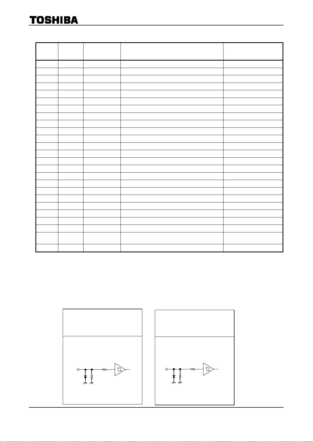
• Built-in input pull-down resistance: 100 kΩ (typ.), (only TQ terminal: 70kΩ(typ.))
• Output monitor pins (ALERT): Maximum of I
ALERT
= 1 mA
• Output monitor pins (MO): Maximum of I
MO
= 1 mA
• Equipped with reset and enable pins
• Stand by function
• Single power supply
• Built-in thermal shutdown (TSD) circuit
• Built-in under voltage lock out (UVLO) circuit
• Built-in over-current detection (ISD) circuit
TB6600HG
Weight:
HZIP25-P-1.00F: 7.7g (typ.)
HZIP25-P-1.00F
TB6600HG
2016-06-10
2
Pin No.
I/O Symbol Functional Description Remark
1 Output ALERT TSD / ISD monitor pin Pull-up by external resistance
2 ― SGND Signal ground
3 Input TQ Torque (output current) setting input pin
4 Input Latch/Auto Select a return type for TSD. L: Latch, H: Automatic return
5 Input Vref
Voltage input for 100% current level
6 Input Vcc Power supply
7 Input M1 Excitation mode setting input pin
8 Input M2 Excitation mode setting input pin
9 Input M3 Excitation mode setting input pin
10 Output OUT2B B channel output 2
11 ― N
FB
B channel output current detection pin
12 Output OUT1B
B channel output 1
13 ― PGNDB
Power ground
14 Output OUT2A
A channel output 2
15 ― N
FA
A channel output current detection pin
16 Output OUT1A
A channel output 1
17 ― PGNDA
Power ground
18 Input ENABLE Enable signal input pin H: Enable, L: All outputs off
19 Input RESET Reset signal input pin L: Initial mode
20 Input Vcc Power supply
21 Input CLK CLK pulse input pin
22 Input CW/CCW Forward/reverse control pin L: CW, H:CCW
23 ― OSC Resistor connection pin for internal oscillation setting
24 Output Vreg Control side connection pin for power capacitor
Connecting capacitor to
SGND
25 Output MO Electrical angle monitor pin Pull-up by external resistance
<Terminal circuits>
Input pins
(M1, M2, M3,CLK, CW/CCW,
ENABLE, RESET, Latch/Auto)
Input pins
(TQ)
10kΩ
100kΩ
V
DD
10kΩ
70kΩ
Pin Functions
TB6600HG
2016-06-10
3
(Top View)
MO
M1
RESET
TQ
ALERT
Vref
PGNDA
CLK
OSC
N
FA
PGNDB
N
FB
M3
23 2511 13 15 17 19 21
16 18 20 22 24
1 3 5 7 9
Vcc
CW/CCW
Vreg
2 4 6 8 10 12 14
SGND
Latch/Auto
Vcc
M2
OUT2B
OUT1B
OUT2A
OUT1A
ENABLE
Pin Assignment
东芝代理、大量现货:QQ 990123167 13610068393
TB6600HG
2016-06-10
4
Setting of Vref
Input
Voltage ratio
TQ
L 30%
H 100%
M1
M2
CW/CCW
CLK
M3
OSC
Input
circuit
1/3
TSD / ISD / UVLO
MO ALERT
H-Bridge
driver A
OUT1A
OUT2A
N
FA
H-Bridge
driver B
OUT1B
OUT2B
N
FB
Vref
SGND PGNDB
Current selector
circuit A
3
4
12
15
14
16
6, 20 1 25 24
7
8
9
22
21
19
18
17 2
Current selector
circuit B
Pre
-drive
Pre
-drive
11
OSC
10
RESET
13
PGNDA
23
5
Latch/Auto
TQ
Vcc Vreg
100%/30%
Reg(5V)
ENABLE
Block Diagram
TB6600HG
2016-06-10
5
Description of Functions
1. Excitation Settings
The excitation mode can be selected from the following eight modes using the M1, M2 and M3 inputs. New
excitation mode starts from the initial mode when M1, M2, or M3 inputs are shifted during motor operation.
In this case, output current waveform may not continue.
Input
Mode
(Excitation)
M1 M2 M3
L L L
Standby mode
(Operation of the internal circuit is almost turned off.)
L L H 1/1 (2-phase excitation, full-step)
L H L
1/2A type (1-2 phase excitation A type)
( 0%, 71%, 100% )
L H H
1/2B type (1-2 phase excitation B type)
( 0%, 100% )
H L L 1/4 (W1-2 phase excitation)
H L H 1/8 (2W1-2 phase excitation)
H H L 1/16 (4W1-2 phase excitation)
H H H
Standby mode
(Operation of the internal circuit is almost turned off.)
Note: To change the exciting mode by changing M1, M2, and M3, make sure not to set M1 = M2 = M3 = L or M1 = M2 =
M3 = H.
Standby mode
The operation mode moves to the standby mode under the condition M1 = M2 = M3 = L or M1 = M2 = M3
= H.
The power consumption is minimized by turning off all the operations except protecting operation.
In standby mode, output terminal MO is HZ.
Standby mode is released by changing the state of M1=M2=M3=L and M1=M2=M3=H to other state.
Input signal is not accepted for about 200 μs after releasing the standby mode.
剩余34页未读,继续阅读
资源评论
KIOXIA铠侠总代
- 粉丝: 282
- 资源: 30
上传资源 快速赚钱
- 我的内容管理 展开
- 我的资源 快来上传第一个资源
- 我的收益 登录查看自己的收益
- 我的积分 登录查看自己的积分
- 我的C币 登录后查看C币余额
- 我的收藏
- 我的下载
- 下载帮助
最新资源
- 937712277954201实习5.word
- 2程序语言基础知识pdf1_1716337722703.jpeg
- 简单的Python示例,演示了如何使用TCP/IP协议进行基本的客户端和服务器通信
- 考试.sql
- keil2 + proteus + 8051.exe
- 1961ee27df03bd4595d28e24b00dde4e_744c805f7e4fb4d40fa3f695bfbab035_8(1).c
- mediapipe-0.9.0.1-cp37-cp37m-win-amd64.whl.zip
- windows注册表编辑工具
- mediapipe-0.9.0.1-cp37-cp37m-win-amd64.whl.zip
- 校园通行码预约管理系统20240522075502
资源上传下载、课程学习等过程中有任何疑问或建议,欢迎提出宝贵意见哦~我们会及时处理!
点击此处反馈
安全验证
文档复制为VIP权益,开通VIP直接复制
信息提交成功