没有合适的资源?快使用搜索试试~ 我知道了~
bh1750光照传感器.pdf
1 下载量 2 浏览量
2024-05-11
09:55:57
上传
评论
收藏 557KB PDF 举报
温馨提示
试读
21页
bh1750
资源推荐
资源详情
资源评论
1/17
www.rohm.com
2011.11 - Rev.D
© 2011 ROHM Co., Ltd. All rights reserved.
Ambient Light Sensor IC Series
Digital 16bit Serial Output Type
Ambient Light Sensor IC
BH1750FVI
●Descriptions
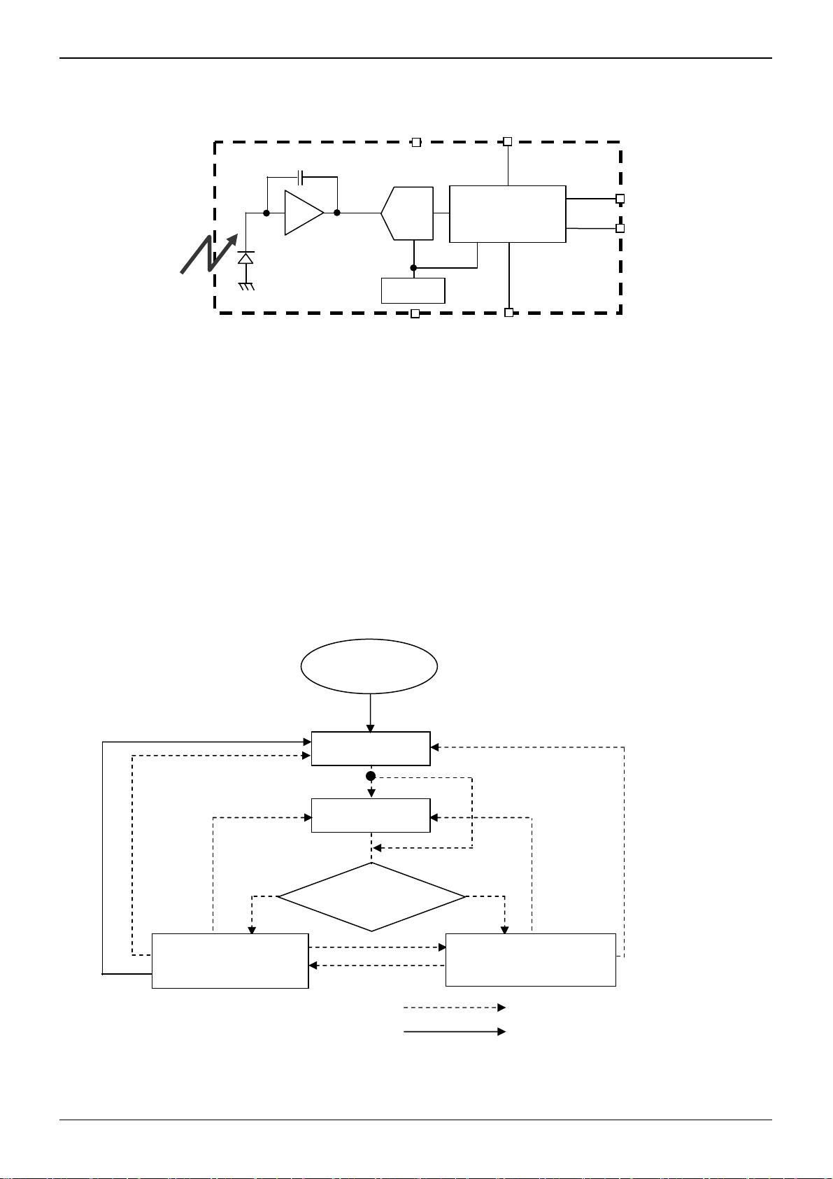
BH1750FVI is an digital Ambient Light Sensor IC for I
2
C bus interface. This IC is the most suitable to obtain the ambient light
data for adjusting LCD and Keypad backlight power of Mobile phone. It is possible to detect wide range at High resolution.
( 1 - 65535 lx ).
●Features
1) I
2
C bus Interface ( f / s Mode Support )
2) Spectral responsibility is approximately human eye response
3) Illuminance to Digital Converter
4) Wide range and High resolution. ( 1 - 65535 lx )
5) Low Current by power down function
6) 50Hz / 60Hz Light noise reject-function
7) 1.8V Logic input interface
8) No need any external parts
9) Light source dependency is little. ( ex. Incandescent Lamp. Fluorescent Lamp. Halogen Lamp. White LED. Sun Light )
10) It is possible to select 2 type of I
2
C slave-address.
11) Adjustable measurement result for influence of optical window
( It is possible to detect min. 0.11 lx, max. 100000 lx by using this function. )
12) Small measurement variation (+/- 20%)
13) The influence of infrared is very small.
●Applications
Mobile phone, LCD TV, NOTE PC, Portable game machine, Digital camera, Digital video camera, PDA,
LCD display
●Absolute Maximum Ratings
Parameter Symbol Ratings Units
Supply Voltage Vmax
4.5 V
Operating Temperature Topr -40~85 ℃
Storage Temperature Tstg -40~100 ℃
SDA Sink Current Imax 7 mA
Power Dissipation Pd 260
※
mW
※ 70mm × 70mm × 1.6mm glass epoxy board. Derating in done at 3.47mW/℃ for operating above Ta=25℃.
●Operating Conditions
Parameter Symbol
Ratings
Units
Min. Typ. Max.
VCC Voltage Vcc 2.4 3.0 3.6 V
I
2
C Reference Voltage VDVI 1.65 - VCC V
No.11046EDT01
BH1750FVI
Technical Note
2/17
www.rohm.com
2011.11 - Rev.D
© 2011 ROHM Co., Ltd. All rights reserved.
●Electrical Characteristics ( VCC = 3.0V, DVI = 3.0V, Ta = 25℃, unless otherwise noted )
Parameter Symbol
Limits
Units Conditions
Min. Typ. Max.
Supply Current Icc1 - 120 190 µA Ev = 100 lx
※
1
Powerdown Current Icc2 - 0.01 1.0 µA No input Light
Peak Wave Length λp - 560 - nm
Measurement Accuracy S/A 0.96 1.2 1.44 times
Sensor out / Actual lx
EV = 1000 lx
※
1,
※
2
Dark ( 0 lx ) Sensor out S0 0 0 3 count H-Resolution Mode
※
3
H-Resolution Mode Resolution rHR - 1 - lx
L-Resolution Mode Resolution rLR - 4 - lx
H-Resolution Mode
Measurement Time
tHR - 120 180 ms
L-Resolution Mode
Measurement Time
t
LR - 16 24 ms
Incandescent /
Fluorescent Sensor out ratio
rI
F - 1 - times
EV = 1000 lx
ADDR Input ‘H’ Voltage VAH 0.7 * VCC - - V
ADDR Input ‘L’ Voltage VAL - - 0.3 * VCC V
DVI Input ‘L’ Voltage VDVL - - 0.4 V
SCL, SDA Input ‘H’ Voltage 1 VIH1 0.7 * DVI - - V DVI ≧ 1.8V
SCL, SDA Input ‘H’ Voltage 2 VIH2 1.26 - - V 1.65V ≦ DVI <1.8V
SCL, SDA Input ‘L’ Voltage 1 VIL1 - - 0.3 * DVI V DVI ≧ 1.8V
SCL, SDA Input ‘L’ Voltage 2 VIL2 - - DVI – 1.26 V 1.65V ≦ DVI < 1.8V
SCL, SDA, ADDR
Input ‘H’ Current
I
IH
- -
10 µA
SCL, SDA, ADDR
Input ‘L’ Current
I
IL
- -
10 µA
I
2
C SCL Clock Frequency fSCL
- -
400 kHz
I
2
C Bus Free Time tBUF 1.3
-
- µs
I
2
C Hold Time ( repeated )
START Condition
t
HDSTA 0.6
-
- µs
I
2
C Set up time
for a Repeated START Condition
t
SUSTA 0.6
-
- µs
I
2
C Set up time
for a Repeated STOP Condition
tSUSTD 0.6
-
- µs
I
2
C Data Hold Time tHDDAT 0
-
0.9 µs
I
2
C Data Setup Time tSUDAT 100
-
- ns
I
2
C ‘L’ Period of the SCL Clock tLOW 1.3
-
- µs
I
2
C ‘H’ Period of the SCL Clock tHIGH 0.6
-
- µs
I
2
C SDA Output ‘L’ Voltage VOL 0
-
0.4 V IOL = 3 mA
※1 White LED is used as optical source.
※2 Measurement Accuracy typical value is possible to change '1' by "Measurement result adjustment function".
※3 Use H-resolution mode or H-resolution mode2 if dark data ( less than 10 lx ) is need.
BH1750FVI
Technical Note
3/17
www.rohm.com
2011.11 - Rev.D
© 2011 ROHM Co., Ltd. All rights reserved.
●Reference Data
0
0.2
0.4
0.6
0.8
1
1.2
-90 -60 -30 0 30 60 90
Angle [ deg ]
Ratio
0
0.2
0.4
0.6
0.8
1
1.2
-90 -60 -30 0 30 60 90
Angle [ deg ]
Ratio
Fig.8 Light Source Dependency
( Fluorescent Light is set to '1' )
1
10
100
1000
10000
100000
1 10 100 1000 10000 100000
Illuminance [ lx ]
Measurement Result
Fig.4 Directional Characteristics 1
Fig.5 Directional Characteristics 2
Fig.6 Dark Response
蛍光灯白熱灯感度比
0
2
4
6
8
10
-40 -20 0 20 40 60 80 100
Ta [
℃
]
Measurement Result
0
50
100
150
200
2 2.5 3 3.5 4
VCC [ V ]
ICC @ Measurement
H-Res.
L-Res.
0
8
16
24
32
40
48
56
64
0 8 16 24 32 40 48 56 64
Illuminance [ lx ]
Measurement Result
H-Res.
L-Res.
H-Res.
-
+
-
+
1pin
1pin
Fig.7 Measurement Accuracy
Temperature Dependency
Fig.2 Illuminance -
Measurement Result 1
Fig.3 Illuminance -
Measuremnet Result 2
Fig.9 VCC - ICC
( During measurement )
Fig.10 VCC – ICC@0 Lx
( POWER DOWN )
Fig.1 Spectral Response
0
0.2
0.4
0.6
0.8
1
1.2
22.533.54
VCC [ V ]
Ratio
Fig.11 Measurement Result
VCC Dependency
0
0.2
0.4
0.6
0.8
1
1.2
1.5 2 2.5 3 3.5
DVI [ V ]
Ratio
Fig.12 Measurement Result
DVI Dependency
DVI=1.8V
VCC=3V
0
0.2
0.4
0.6
0.8
1
1.2
400 500 600 700 800 900 1000 1100
Wavelength [ nm ]
Ratio
00.511.52
Fluorescent
Light
Incandescent
Light
Halogen
Light
Kripton Light
Artifical Sun
Light
White LED
Ratio
0
0.2
0.4
0.6
0.8
1
1.2
-40-200 20406080100
Ta [
℃
]
Ratio
0.01
0.1
1
10
-40 -20 0 20 40 60 80 100
Ta [
℃
]
ICC @ POWER DOWN [ uA ]
-
+
-
+
BH1750FVI
Technical Note
4/17
www.rohm.com
2011.11 - Rev.D
© 2011 ROHM Co., Ltd. All rights reserved.
●Block Diagram
●Block Diagram Descriptions
・PD
Photo diode with approximately human eye response.
・AMP
Integration-OPAMP for converting from PD current to Voltage.
・ADC
AD converter for obtainment Digital 16bit data.
・Logic + I
2
C Interface
Ambient Light Calculation and I
2
C BUS Interface. It is including below register.
Data Register → This is for registration of Ambient Light Data. Initial Value is "0000_0000_0000_0000".
Measurement Time Register → This is for registration of measurement time. Initial Value is "0100_0101".
・OSC
Internal Oscillator ( typ. 320kHz ). It is CLK for internal logic.
●Measurement Procedure
* "Power On" Command is possible to omit.
SCL
SDA
GND
ADDR
PD
VCC
DVI
Logic
+
I
2
C Interface
ADC
AMP
OSC
State Transition by I
2
C write-command.
Automatically State Transition
State is automatically changed to
Power Down mode.
Power supply
Power Down
Power On
Measurement Command
Initial state is Power Down mode after
VCC and DVI supply.
One Time Measurement
Continuous Measurement
BH1750FVI
Technical Note
5/17
www.rohm.com
2011.11 - Rev.D
© 2011 ROHM Co., Ltd. All rights reserved.
●Instruction Set Architecture
Instruction Opecode Comments
Power Down 0000_0000
No active state.
Power On 0000_0001
Waiting for measurement command.
Reset 0000_0111
Reset Data register value. Reset command is not acceptable in
Power Down mode.
Continuously H-Resolution Mode 0001_0000
Start measurement at 1lx resolution.
Measurement Time is typically 120ms.
Continuously H-Resolution Mode2 0001_0001
Start measurement at 0.5lx resolution.
Measurement Time is typically 120ms.
Continuously L-Resolution Mode 0001_0011
Start measurement at 4lx resolution.
Measurement Time is typically 16ms.
One Time H-Resolution Mode 0010_0000
Start measurement at 1lx resolution.
Measurement Time is typically 120ms.
It is automatically set to Power Down mode after measurement.
One Time H-Resolution Mode2 0010_0001
Start measurement at 0.5lx resolution.
Measurement Time is typically 120ms.
It is automatically set to Power Down mode after measurement.
One Time L-Resolution Mode 0010_0011
Start measurement at 4lx resolution.
Measurement Time is typically 16ms.
It is automatically set to Power Down mode after measurement.
Change Measurement time
( High bit )
01000_MT[7,6,5]
Change measurement time.
※ Please refer "adjust measurement result for influence of optical window."
Change Masurement time
( Low bit )
011_MT[4,3,2,1,0]
Change measurement time.
※ Please refer "adjust measurement result for influence of optical window."
※ Don't input the other opecode.
●Measurement mode explanation
Measurement Mode Measurement Time. Resolurtion
H-resolution Mode2 Typ. 120ms. 0.5 lx
H-Resolution Mode Typ. 120ms. 1 lx.
L-Resolution Mode Typ. 16ms. 4 lx.
We recommend to use H-Resolution Mode.
Measurement time ( integration time ) of H-Resolution Mode is so long that some kind of noise( including in 50Hz / 60Hz
noise ) is rejected. And H-Resolution Mode is 1 l x resolution so that it is suitable for darkness ( less than 10 lx )
H-resolution mode2 is also suitable to detect for darkness.
●Explanation of Asynchronous reset and Reset command "0000_0111"
1) Asynchronous reset
All registers are reset. It is necessary on power supply sequence. Please refer "Timing chart for VCC and DVI power
supply sequence" in this page. It is power down mode during DVI = 'L'.
2) Reset command
Reset command is for only reset Illuminance data register. ( reset value is '0' ) It is not necessary even power supply
sequence.It is used for removing previous measurement result. This command is not working in power down mode, so
that please set the power on mode before input this command.
剩余20页未读,继续阅读
资源评论
zhusl6688
- 粉丝: 1164
- 资源: 224
上传资源 快速赚钱
- 我的内容管理 展开
- 我的资源 快来上传第一个资源
- 我的收益 登录查看自己的收益
- 我的积分 登录查看自己的积分
- 我的C币 登录后查看C币余额
- 我的收藏
- 我的下载
- 下载帮助
最新资源
- 基于STM32驱动MLX90614红外测温模块和OLED屏幕,测温的同时如果超过37度会在屏幕上显示报警信息
- Stability.postman-collection.json
- SQL 语言入门篇-最常用 SQL 语句大全
- mysql查询语句汇总.zip
- typora-x64-v0.9.93,windows,64位,markdown工具,文本编辑器
- 基于C语言的neon_osd_Draw ARM Neon加速OSD点阵设计源码
- 目标检测-工地工人安全设备佩戴检测数据集-3500张图-+对应VOC-COCO-YOLO三种格式标签+数据集划分脚本+训练日志
- 运筹学运输问题综合实验的实验报告
- home - 副本.vue
- imageProcess.py
资源上传下载、课程学习等过程中有任何疑问或建议,欢迎提出宝贵意见哦~我们会及时处理!
点击此处反馈
安全验证
文档复制为VIP权益,开通VIP直接复制
信息提交成功