


CRSF Protocol
14.08.2017 Rev 07
Table of content
Table of content
Features
Hardware
Single wire half duplex UART
Dual wire / full duplex UART
Multimaster I2C (BST)
Frame
Structure
Device addresses
CRC
Routing
Frame Types
Broadcast frames
0x02 GPS
0x08 Battery sensor
0x0B Heartbeat
0x0F Video transmitter
0x14 Link statistics
0x16 RC channels packed
0x1E Attitude
0x21 Flight mode text based
Extended header frames
0x28 Parameter ping devices
0x29 Parameter device information
0x2B Parameter settings (entry)
0x2C Parameter settings (read)
0x2D Parameter value (write)
Chunks
Parameter type definitions and hidden bit
Commands
0x32 Command frame

0x01 FC Commands:
0x03 Bluetooth Command
0x05 OSD Commands:
0x08 VTX Commands:
0x09 LED
0x0A Firmware Update:
0x10 RC Receiver
0x78 - 0x79 KISS FC
Changelog
Rev 07
Rev 06
Rev 05
Rev 04
Rev 03
Rev 02
Features
● Low latency high update rate for RC signals between RC - XF and XF - FC
● Bidirectional communication
● Share telemetry from flying platform to the RC
● Edit configuration for direct connected devices and remotely connected devices (RC
can configure FC or OSD over crossfire)
● Share receiver serial number to TX so it can be matched to model memory.
Future features:
● System should be able to handle multiple of the same sensors using sensor ID’s
Hardware
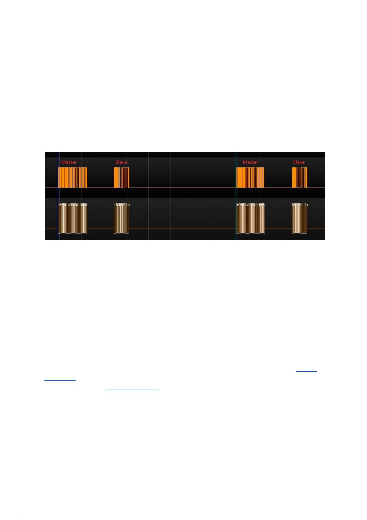
Single wire half duplex UART
This configuration is usually used between RC and Crossfire TX. XF TX support both
inverted and non-inverted UART. The RC acts as master in this case and the XF TX can
only send telemetry if it’s synchronized to the RC frames sent by the RC. The RC frame
update rate should not be sent more often than every 4ms. The UART runs at 416kbaud
8N1 ( inverted or non-inverted ) at 3.3V level.
Dual wire / full duplex UART
This configuration is usually used on the flying platform side. Two devices are connected by
regular UART connection. Only non-inverted ( regular ) UART is supported in this
configuration. The UART runs at 416kbaud 8N1 at 3.0 to 3.3V level.
Multimaster I2C (BST)
BST is a multimaster I2C bus. It runs at 3.3V level at 100kHz using 7 bit addresses. Device
addresses already contain the R/W bit. Which means the list is each device’s write address
and read address is Device addresses + 1.
Each device supporting BST should release SDA in any case to not block the bus. It’s
recommended to monitor the heartbeat message and reset the interface if there is a timeout
>1.5s. It’s required to support general call frames which will be called broadcast frames
within this document.

Frame
Structure
The basic structure for each frame is the same. There is a range of Types with an extended
header which will have the first few bytes of payload standardized. This is required to route
frame across multiple devices for point to point communication.
Broadcast Frames:
<Device address or Sync Byte> <Frame length> <Type><Payload> <CRC>
Extended header frames:
<Device address or Sync Byte> <Frame length> <Type><Destination Address> <Origin
Address> <Payload> <CRC>
Device address or Sync Byte: (uint8_t) Device address for I2C or Sync byte serial
connections.In case of I2C (BST) this is mostly “Broadcast
address” or defined by Router.
Frame length: Amount of bytes including Type, Payload and CRC (uint8_t)
Type: Frame type (uint8_t)
CRC: 8 Bit CRC of the frame. See CRC (uint8_t)
Sync Byte: 0xC8
Endianness Big endian
Device addresses
0x00 Broadcast address
0x10 USB Device
0x12 Bluetooth Module
0x80 TBS CORE PNP PRO
0x8A Reserved
0xC0 PNP PRO digital current sensor
0xC2 PNP PRO GPS
0xC4 TBS Blackbox
0xC8 Flight controller
0xCA Reserved
0xCC Race tag
0xEA Radio Transmitter
0xEB Reserved
0xEC Crossfire / UHF receiver
0xEE Crossfire transmitter
电流计
设备
蓝牙设备
保留位
飞行控制
发射信号
通道值信号
发送字节
校验
有效数据
类型
目标地址
起始地址
发送数据格式
扩展型 数据格式
设备地址或同步字节
设备地址或同步字节

CRC
CRC includes Type and Payload of each frame.
Code example:
/* CRC8 implementation with polynom = x
7
+ x
6
+ x
4
+ x
2
+ x
0
(0xD5) */
unsigned char crc8tab[256] = {
0x00, 0xD5, 0x7F, 0xAA, 0xFE, 0x2B, 0x81, 0x54, 0x29, 0xFC, 0x56, 0x83, 0xD7, 0x02, 0xA8, 0x7D,
0x52, 0x87, 0x2D, 0xF8, 0xAC, 0x79, 0xD3, 0x06, 0x7B, 0xAE, 0x04, 0xD1, 0x85, 0x50, 0xFA, 0x2F,
0xA4, 0x71, 0xDB, 0x0E, 0x5A, 0x8F, 0x25, 0xF0, 0x8D, 0x58, 0xF2, 0x27, 0x73, 0xA6, 0x0C, 0xD9,
0xF6, 0x23, 0x89, 0x5C, 0x08, 0xDD, 0x77, 0xA2, 0xDF, 0x0A, 0xA0, 0x75, 0x21, 0xF4, 0x5E, 0x8B,
0x9D, 0x48, 0xE2, 0x37, 0x63, 0xB6, 0x1C, 0xC9, 0xB4, 0x61, 0xCB, 0x1E, 0x4A, 0x9F, 0x35, 0xE0,
0xCF, 0x1A, 0xB0, 0x65, 0x31, 0xE4, 0x4E, 0x9B, 0xE6, 0x33, 0x99, 0x4C, 0x18, 0xCD, 0x67, 0xB2,
0x39, 0xEC, 0x46, 0x93, 0xC7, 0x12, 0xB8, 0x6D, 0x10, 0xC5, 0x6F, 0xBA, 0xEE, 0x3B, 0x91, 0x44,
0x6B, 0xBE, 0x14, 0xC1, 0x95, 0x40, 0xEA, 0x3F, 0x42, 0x97, 0x3D, 0xE8, 0xBC, 0x69, 0xC3, 0x16,
0xEF, 0x3A, 0x90, 0x45, 0x11, 0xC4, 0x6E, 0xBB, 0xC6, 0x13, 0xB9, 0x6C, 0x38, 0xED, 0x47, 0x92,
0xBD, 0x68, 0xC2, 0x17, 0x43, 0x96, 0x3C, 0xE9, 0x94, 0x41, 0xEB, 0x3E, 0x6A, 0xBF, 0x15, 0xC0,
0x4B, 0x9E, 0x34, 0xE1, 0xB5, 0x60, 0xCA, 0x1F, 0x62, 0xB7, 0x1D, 0xC8, 0x9C, 0x49, 0xE3, 0x36,
0x19, 0xCC, 0x66, 0xB3, 0xE7, 0x32, 0x98, 0x4D, 0x30, 0xE5, 0x4F, 0x9A, 0xCE, 0x1B, 0xB1, 0x64,
0x72, 0xA7, 0x0D, 0xD8, 0x8C, 0x59, 0xF3, 0x26, 0x5B, 0x8E, 0x24, 0xF1, 0xA5, 0x70, 0xDA, 0x0F,
0x20, 0xF5, 0x5F, 0x8A, 0xDE, 0x0B, 0xA1, 0x74, 0x09, 0xDC, 0x76, 0xA3, 0xF7, 0x22, 0x88, 0x5D,
0xD6, 0x03, 0xA9, 0x7C, 0x28, 0xFD, 0x57, 0x82, 0xFF, 0x2A, 0x80, 0x55, 0x01, 0xD4, 0x7E, 0xAB,
0x84, 0x51, 0xFB, 0x2E, 0x7A, 0xAF, 0x05, 0xD0, 0xAD, 0x78, 0xD2, 0x07, 0x53, 0x86, 0x2C, 0xF9};
uint8_t crc8(const uint8_t * ptr, uint8_t len)
{
uint8_t crc = 0;
for (uint8_t i=0; i<len; i++) {
crc = crc8tab[crc ^ *ptr++];
}
return crc;
}


