Page 2
confidential
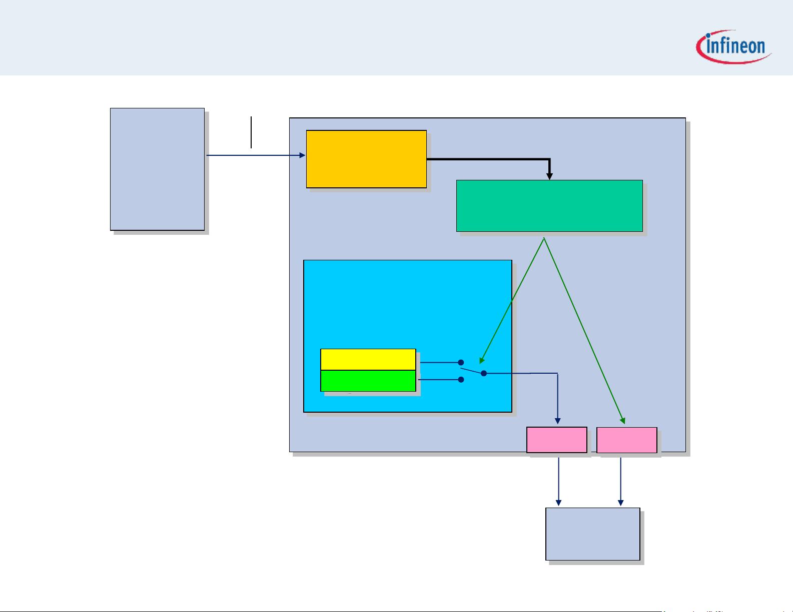
Exercise GPTA_LTC_PWM
Objective
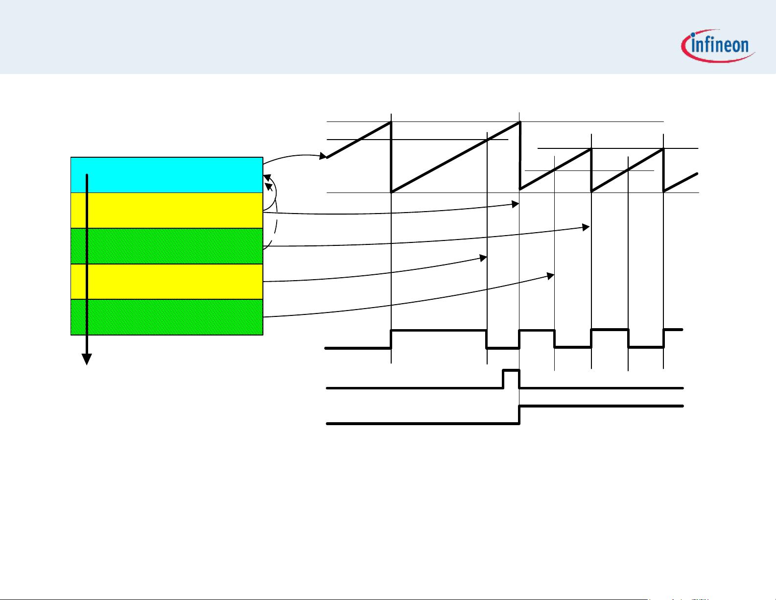
Using 5 Local Timer Cells (LTC), generate a PWM signal with switchable
duty cycle and period (Signal 0 and Signal 1).
Signal 0 has a period of 100us and a duty cycle of 20%,signal 1 has a
period of 200us and a duty cycle of 75%.
Every time the user strikes a key on its keyboard (using MTTY), the
signal toggles from one duty cycle / period configuration to the other.
The character is also echoed back to the PC.
The update of the duty cycle / period is fully coherent and is observed on
a scope.
Let‟s get started now!