


Freescale Semiconductor Document Number:
Application Note Rev. C, 1/2012
© Freescale Semiconductor, Inc., 2009-2012. All rights reserved.
Freescale Preliminary—Subject to Change Without Notice
i.MX IOMUX Design Aid
(User’s Guide for IOMux.exe)
by David DiCarlo
Multimedia Applications Division
Freescale Semiconductor, Inc.
Austin, TX
Package pin count limitations require each device in the i.MX
family to have an I/O multiplexer (IOMUX) in order to facilitate
the connection of internal peripheral signals to the external system.
The IOMUX module allows up to 8 internal signals to be
connected to a single I/O pad on a device.
In order to ease the assignment of internal signals to external
device balls/pins, the IOMux design aid tool was developed.
IOMux.exe can be used to make signal assignments for supported
i.MX devices. The tool identifies and assists in the resolution
conflicts as they arise in real-time.
The tool allows notes or comments for each signal to be added to
the list of assignments. Design configurations can be saved for
future use and the exported for use in schematics.
The tool can also be used to generate C code to configure the
IOMUXC registers according to the users design. This alleviates
software developers from the tedious task of comparing schematics
to the i.MX Reference Manual to establish connections to
peripherals and also serves as supplementary documentation of a
system.
This document is intended to provide the user a guide to use of this
system design aid.

2 Freescale Semiconductor
Freescale Preliminary—Subject to Change Without Notice
Table of Contents
1 Introduction ................................................................ 3
2 Application Overview .................................................. 4
2.1 Menus ................................................................. 4
2.2 Signal Selection Pane ......................................... 4
2.3 Search Box ......................................................... 5
2.4 Assigned Signals Tab ......................................... 5
2.5 Ball Diagram Tab ................................................ 6
2.6 Pads Tab............................................................. 6
2.7 Registers Tab ...................................................... 7
2.8 Power Tab........................................................... 7
2.9 General Tab ........................................................ 7
2.10 Title Bar............................................................... 8
2.11 Status Bar ........................................................... 8
3 Menus ........................................................................ 8
3.1 File Menu ............................................................ 8
3.1.1 Open ................................................................................................................................................................................................................... 8
3.1.2 Save .................................................................................................................................................................................................................... 9
3.1.3 Save As .............................................................................................................................................................................................................. 9
3.1.4 Print .................................................................................................................................................................................................................... 9
3.1.5 Import ->Import IOMux Tool v3.0 design file ................................................................................................................................................. 9
3.1.6 Export -> Export to .csv .................................................................................................................................................................................. 10
3.1.7 Export -> Export to .rtf / Export to .txt ........................................................................................................................................................... 10
3.1.8 Exit .................................................................................................................................................................................................................... 10
3.2 Device Menu ..................................................... 11
3.3 Code Menu ....................................................... 12
3.3.1 Basic ................................................................................................................................................................................................................. 12
3.3.2 Expanded Fields ............................................................................................................................................................................................. 14
3.3.3 Commented Selections .................................................................................................................................................................................. 15
3.3.4 Full Comments ................................................................................................................................................................................................ 17
3.3.5 Generate Code ................................................................................................................................................................................................ 22
3.4 View Menu ........................................................ 23
3.4.1 Shared Pins and Signal Comments.............................................................................................................................................................. 23
3.4.2 Auto-Detect Conflicts ...................................................................................................................................................................................... 23
3.4.3 Update Conflicts .............................................................................................................................................................................................. 23
3.5 Help Menu......................................................... 24
4 Basic Usage Example with Explanation ................... 25
4.1 Select Peripherals and Signals for the Board Design 25
4.2 Resolve Conflicting Signals by Selecting Alternate Pads 27
4.3 Add Comments to Signals for Reference .......... 28
4.4 Ball Diagram View ............................................. 30
4.5 Setup IOMUXC Registers ................................. 30
4.6 Setup Power Groups ......................................... 32
4.7 Enter Board Design Info on the General Tab .... 34
4.8 Save the Design ................................................ 35
4.9 Generating IOMUXC Configuration Code ......... 36
5 Advanced Usage Example with Explanation ............ 37
5.1 GPS Signals on the i.MX6DQ Sabre Tablet Reference Board 37
5.2 Create a New Module ....................................... 39
5.3 Drag GPS Signals to New ‘gps’ Module ............ 40
Revision History .............................................................. 41

Freescale Semiconductor 3
Freescale Preliminary—Subject to Change Without Notice
1 Introduction
Each device in the i.MX family has a wealth of on-chip peripherals to use in an application with many
more signals available to connect to the outside world. Not all the signals of each on-chip peripheral
needs to be connected in every application. Some peripherals are not even used in many applications.
The IOMUX module was designed to minimize a device’s pin count to keep the package cost and
complexity down by providing a configurable switch matrix between on-chip signals and the external
system. Each ball (or pin) of an i.MX device may be connected to one of up to eight internal signals by
the IOMUX.
The IOMux design aid was developed to address several challenges: One of the challenges in designing
an i.MX device into an application is in the assignment of internal signals to external signals. Another
challenge is verifying connectivity of devices on a newly designed and assembled printed circuit board.
Lastly, conveying the hardware configuration to software developers such that the internal signals may
be connected by the initialization code to the proper external traces without them having to reverse
engineer from the schematic may pose a challenge as well.
In order to use the IOMux.exe application, the user is required to be using Microsoft Windows XP or
newer with Microsoft’s .NET Framework, version 4.0 or newer installed. The IOMux application
currently supports the following devices in all the available package variations: i.MX6Dual/Quad.
The IOMux application allows the user to iteratively assign signals and resolve conflicts with other
signals in real time. A system design may be saved for later use or modification, saved to plain or
formatted text, or printed out onto paper.
The IOMux application can also be used to programmatically generate C code to configure the
IOMUXC registers according to the board designer’s mux selections. Armed with the board designer’s
IOMux design file, software developers can automatically generate the source code and header files
necessary to route internal signals to the proper external peripheral connection.
4 Freescale Semiconductor
Freescale Preliminary—Subject to Change Without Notice
2 Application Overview
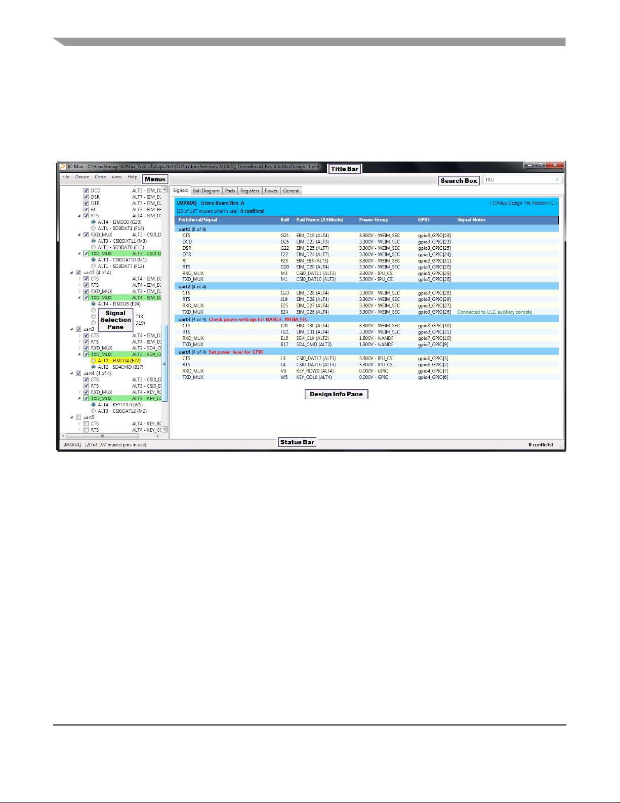
Figure 1 shows a screen shot of the IOMux application window. In the figure, various areas are labeled.
The following subsections describe each area and its features.
Figure 1. IOMux.exe application window overview
2.1 Menus
As with any normal graphical application, the IOMux application has a menu bar in the upper left-hand
region of the application window. The menus are used to select the i.MX device for a design, open/save
design files, and to change view settings.
2.2 Signal Selection Pane
The Signal Selection pane is where most of the action in the IOMux tool takes place. Once an i.MX
device is selected, the Signal Selection pane is populated with all of the IOMUX options for that device
and package combination.
By default, all signals are initially unassigned. Signals are assigned by clicking in the check box next to
a peripheral group or, when expanded, an individual signal.
When a signal exits the i.MX device in more than one place, the ALT-mode/Ball combination desired
may be selected by expanding (clicking the “+” next to the signal name). By default, the first ALT-

Freescale Semiconductor 5
Freescale Preliminary—Subject to Change Without Notice
mode/Ball combination is the one selected. Choose a different assignment by clicking the radio button
next to the ALT-mode/Ball combination.
Normally, the background color in is white. When a conflicting assignment is selected, all conflicting
signals, ALT-mode/Ball assignments and corresponding lines in the Assigned Signals tab are
highlighted in orange. Unassigned ALT-mode/Ball combinations for a signal that will conflict with
other existing assignments are highlighted in yellow.
When the mouse is hovered over a signal name or an ALT-mode/Ball combination, a pop-up tooltip
containing the list of all other internal signals that may be assigned to that ALT-mode/Ball combination
appears. Any conflicting assignments are bolded in the list.
Right-clicking on a peripheral group or a signal brings up a contextual menu to toggle whether that
peripheral or signal is excluded from the design. This may be used to signify that these signals have
been considered for the design but for whatever reason have been used. This feature may also be used in
order to prevent signals within a peripheral group from being assigned when the checkbox at the
peripheral level is selected.
2.3 Search Box
The Search Box is available to perform a simple textual search for full or partial signal names or
package ball/pin IDs. It is useful for quickly finding an item of interest. Note that the text search is not
case sensitive nor is it a very intelligent search: it’s just a basic string search. Search hits show up in the
Signal Selection pane highlighted in green. Figure 1 shows the partial results of a search for the text
“TXD”.
2.4 Assigned Signals Tab
The Assigned Signals tab contains the list of all currently assigned signals in the current design. This
tab is selected by default but it may be selected by clicking in the “Signals” tab if the alternate “Ball
Diagram” tab is displayed. The columns descriptions are listed below:
Peripheral/Signal: This column contains the peripheral and signal names. The
peripheral/module names and the related signals come from the IOMUXC chapter of the
device’s Reference Manual.
Ball: This column contains the package ball/pin assigned to the each signal.
Pad Name (AltMode): This column contains the package ball/pin name and ALT-mode
assigned to the each signal.
Power Group: The Power Group column is provided to view the power rail associated with
selected pad. The voltage level and power group are both listed separated by a hyphen. The
power groups should be assigned using the Power tab of the Design Info Pane. The IOMux
application checks for two power conditions for each peripheral. The warning, “Set power level
for <PowerGroupName>” is displayed if a signal’s power group voltage level is zero. The
warning, “Check power settings for <PowerGroup1Name>, <PowerGroup2Name>” is displayed
if the voltage level for all the signals for the peripheral are not equal. The warning message is
shown in red on the peripheral line in the Design Info Pane. If there is no warning message on


