
www.austriamicrosystems.com/AS5134 Revision 2.3 2 - 32
AS5134
Datasheet - Contents
Contents
1 General Description .................................................................................................................................................................. 1
2 Key Features............................................................................................................................................................................. 1
3 Applications............................................................................................................................................................................... 1
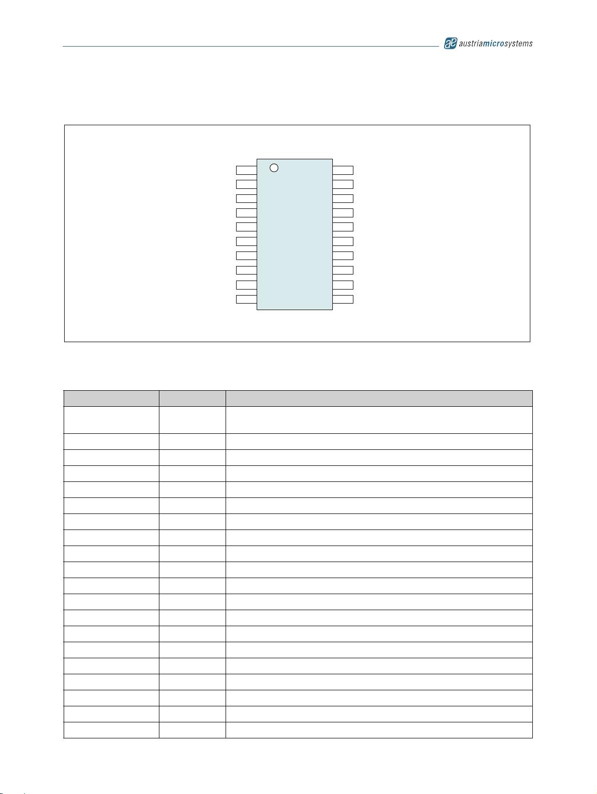
4 Pin Assignments ....................................................................................................................................................................... 3
4.1 Pin Descriptions.................................................................................................................................................................................... 3
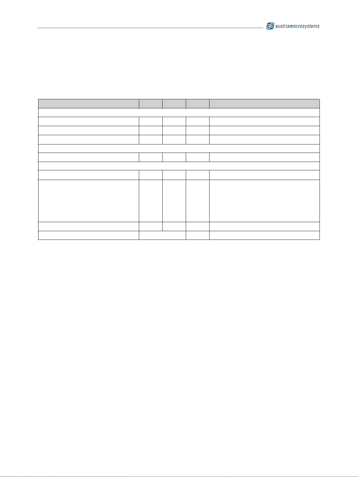
5 Absolute Maximum Ratings ...................................................................................................................................................... 4
6 Electrical Characteristics........................................................................................................................................................... 5
6.1 Timing Characteristics .......................................................................................................................................................................... 6
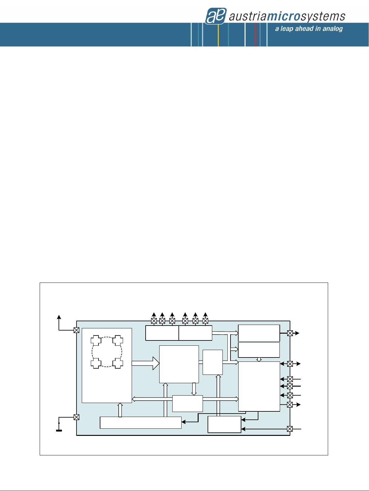
7 Detailed Description.................................................................................................................................................................. 7
7.1 Connecting the AS5134........................................................................................................................................................................ 7
7.2 Serial 3-Wire R/W Connection.............................................................................................................................................................. 8
7.3 Serial 3-Wire Read-only Connection .................................................................................................................................................... 9
7.4 Serial 2-Wire Connection (R/W Mode) ............................................................................................................................................... 10
7.5 Serial 2-Wire Differential SSI Connection........................................................................................................................................... 11
7.6 1-Wire PWM Connection .................................................................................................................................................................... 12
7.7 Analog Output..................................................................................................................................................................................... 14
7.8 Quadrature A/B/Index Output............................................................................................................................................................. 14
7.9 Brushless DC Motor Commutation Mode........................................................................................................................................... 15
7.10 Daisy Chain Mode ............................................................................................................................................................................ 15
7.11 Serial Synchronous Interface (SSI) .................................................................................................................................................. 18
7.12 Redundancy ..................................................................................................................................................................................... 20
8 Application Information ........................................................................................................................................................... 21
8.1 AS5134 Programming ........................................................................................................................................................................ 21
8.1.1 OTP Programming Connection.................................................................................................................................................. 21
8.1.2 Programming Verification .......................................................................................................................................................... 22
8.2 AS5134 Status Indicators................................................................................................................................................................... 24
8.2.1 Lock Status Bit........................................................................................................................................................................... 24
8.2.2 Magnetic Field Strength Indicators ............................................................................................................................................ 24
8.3 Multi Turn Counter.............................................................................................................................................................................. 25
8.4 High Speed Operation ........................................................................................................................................................................ 25
8.4.1 Propagation Delay ..................................................................................................................................................................... 25
8.4.2 Digital Readout Rate.................................................................................................................................................................. 26
8.4.3 Low Power Mode ....................................................................................................................................................................... 26
9 Package Drawings and Markings ........................................................................................................................................... 27
9.1 Recommended PCB Footprint............................................................................................................................................................ 29
10 Ordering Information............................................................................................................................................................. 31


评论0