没有合适的资源?快使用搜索试试~ 我知道了~
各种连接器,封装尺寸
5星 · 超过95%的资源 需积分: 50 145 下载量 87 浏览量
2012-06-01
14:24:10
上传
评论
收藏 2.81MB PDF 举报
温馨提示
试读
35页
各种连接器,封装尺寸
资源推荐
资源详情
资源评论
TABLE OF C
ONTENTS
Page 1
Description Page
IC Socket/PGA Socket/PLCC/Screw Machine Pin 2~16
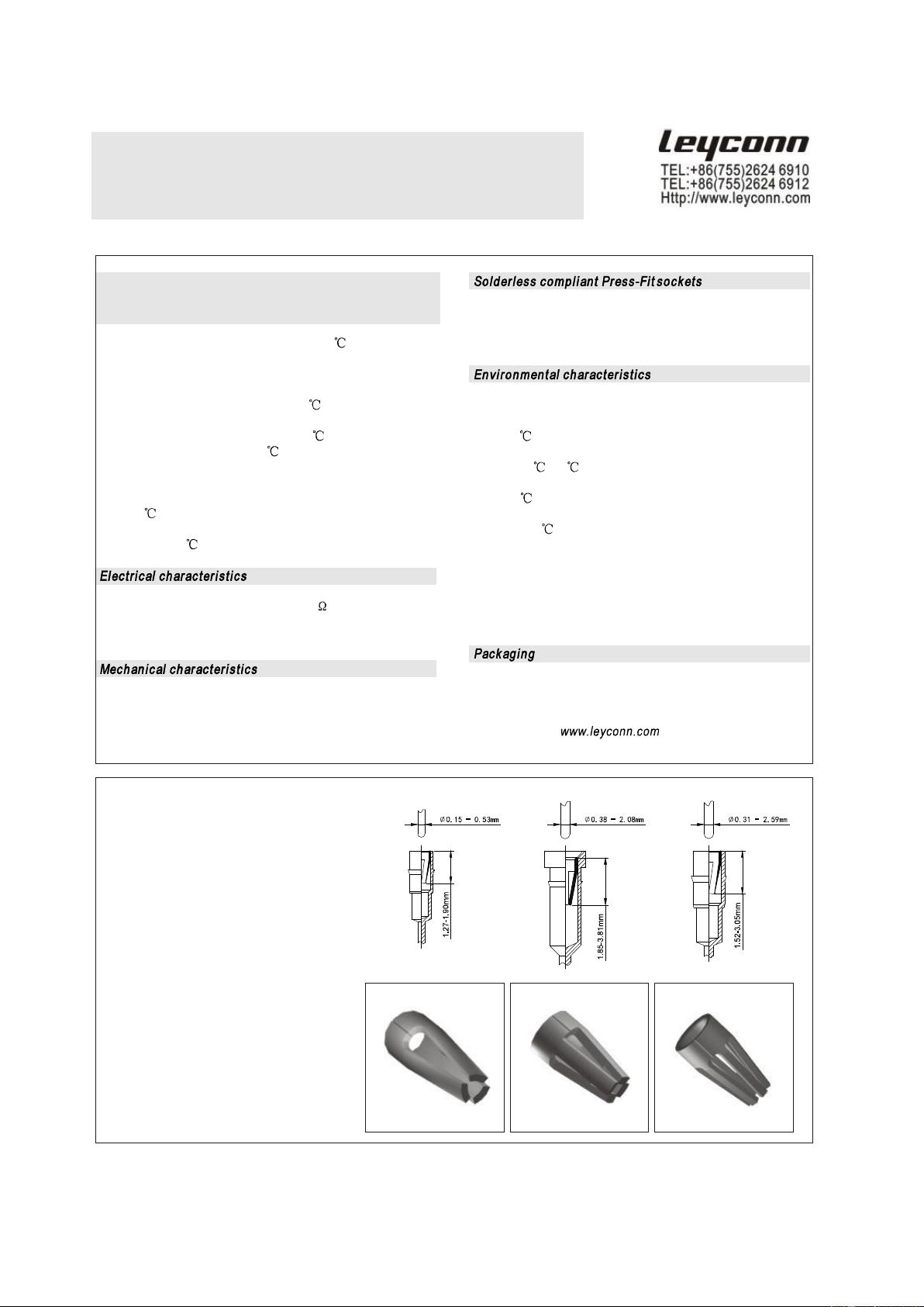
IC Socket Technology Information 2
2.54mm IC Sockets / IC Socket Adapter 3
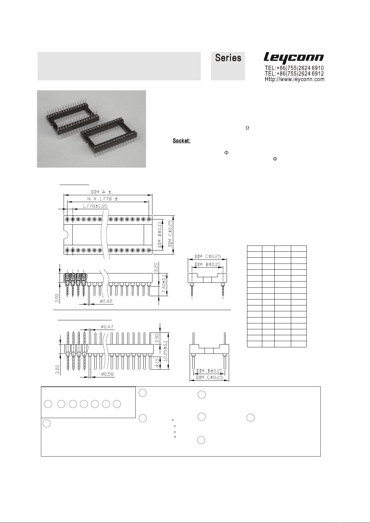
1.778mm IC Socket / IC Socket Adapter 4
2.54mm PIN Connectors 5
2.54mm SIP Socket (Mating Pin 0.76mm) 6
2.54mm SIP Socket (Mating Pin 0.47mm) 7
2.54mm SIP Socket & PIN Connectors (Ultra Low) 8
2.00mm SIP Socket / PIN Connectors 9
1.778mm SIP Socket / PIN Connectors 10
1.27mm SIP Socket 11
1.27mm Pin Connectors 12
2.54mm Pin Grid Arrays & Adapter 13
Chip Carrier Sockets for PLCC 14
Screw Machine Pin - Printed Circuit Pins 15
Screw Machine Pin - Pin Receptacles 16
PIN Header 17~26
1.00mm Pin Header 17
1.27mm Pin Header Straight DIP 18
1.27mm Pin Header Right Angle Type 19
1.27mm Pin Header S.M.T Type 20
2.00mm Pin Header Straight DIP 21
2.00mm Pin Header Right Angle Type 22
2.00mm Pin Header S.M.T Type 23
2.54mm Pin Header Straight DIP 24
2.54mm Pin Header Right Angle Type 25
2.54mm Pin Header S.M.T Type 26
Female Header 27~38
1.00mm Female Header 27
1.27mm Female Header S.M.T Type 28
1.27mm Female Header W/P S.M.T Type 29
1.27mm Female Header Straight DIP Type 30
1.27 x 2.54mm Female Header Straight DIP Type 31
2.00mm Female Header S.M.T Type 32
2.00mm Female Header Straight DIP Type 33
2.00mm Female Header Right Angle Type 34
2.00mm Female Header Bottom Entry Type 35
2.54mm Female Header Straight / Right Angle Type 36
2.54mm Female Header DIP / S.M.T Type 37
2.54mm Female Header Bottom Entry Type 38
Box Header / Ejector Header / I.D.C 39~44
1.27 x 1.27mm Box Header 39
1.27 x 2.54mm Box Header 40
2.00mm Box Header 41
2.00mm Ejector Header
42
Description Page
2.54mm Box Header / Ejector Header
43
I.D.C Socket:1.27 / 2.00 / 2.54mm 44
DIN 41612 Eurocard Connector 45~48
DIN 41612 Eurocard Connector 3-96 Pin 45
DIN 41612 Eurocard Connector 3-48 Pin 46
DIN 41612 Eurocard Connector 2-64 Pin 47
DIN 41612 Eurocard Connector 2-32 Pin 48
Board Mount
Telephone
Modular Jacks 49~55
49
50
51
52
S 53
54
55
USB / Mini USB Connector 56~57
USB Type-A Receptacle Connector 56
Mini USB Receptacle Connector 57
HDMI Connector 58~59
HDMI Connector (With Flange) 58
HDMI Connector (Without
Flange) 59
D subminiature Connector 60~66
High Density Right Angle DIP Solder D-Sub 60
High Density Cup Solder D-Sub 61
High Density DIP Solder D-Sub 62
8.10mm Footprint Right Angle DIP Solder D-Sub 63
Straight Cup Solder D-Sub 64
Straight DIP
Solder D-Sub 65
DVI Right Angle Digital Connector 66
FFC / FPC Connector 67~69
0.5mm SMT
ZIF FFC/FPC Downside Type Conn. 67
0.5mm SMT ZIF FFC/FPC Vertical Type Conn. 68
1.0mm DIP LIF FFC/FPC Top Entry Connector 69
Wire to Board Connector 70~76
1.25mm Wire to Board Connector 70
2.00mm Wire to Board Connector 71
2.00mm Wire to Board Connector 72
2.50mm Wire to Board Connector 73
2.54mm Wire to Board Connector 74
3.96mm Wire to Board Connector 75
3.96mm Wire to
Board Connector 76
Optional Panel Ground
Out Shield, Contacts: 8,10
Right Angle / Straight, Shield, Contacts: 8,10
Right Angle /Straight, Contacts: 4, 6, 8
Right Angle, Contacts: 4, 6, 8
traight, Contacts: 4, 6, 8
Right Angle, Contacts: 4, 6
Right Angle, Ports: 1, 2, 4, 6, 8
Http://www.leyconn.com
Technology Informaiting
IC socket / PCB Connectors / PGA Socket / PLCC Socket
Pitch:2.54mm / 2.00m / 1.778mm /1.27mm
/ 1.00mm
The values listed below are general
specs applying for
LEYCONN socket and pin connectors. Please see individual
catalog page for additional and product specific technical data.
- Operating temperature
range: -55 ...
+125
- Climatic category (IEC): 55/125/21
- Operating humidity
range: annual mean
75 %
- Max working voltage: 100 VRMS/150 VDC (2.54 mm grid)
- Solderability IEC 60068-2-20.Ta: 235 , 2 s
- Resistance to soldering heat IEC 60068-2-20.Tb:
- Through hole mount components: 260 , 5 s
- SMD mount components: 280 , 10 s
- Resistance to corrosion:
1) Salt spray
test IEC 60068-2-1
1.Ka: 48 h
2) Sulfur dioxide (SO2) test IEC 60068-2-42 Kc: 96 h at 25 ppm
SO2, 25 , 75 %rH
3) Hydrogen sulfide (H2S) test IEC 60068-2-43 Kd: 96 h at
12 ppm H2S, 25
, 75 %rH
- Insulation resistance between
any two adjacent contacts: min 10000 M at 500 V AC
- Capacitance between any two
adjacent contacts: max
1 pF
- Clip retention: min. 40 N (no displacement
under axial force applied)
- Contact (sleeve / clip) retention: min. 3.3 N acc. to
MIL-DTL-83734, pt 4.6.4.2
- Press-fit characteristics measured acc. to IEC 60352-5:
- Press-in force: 90 N max. (at min. hole dia.) / 65 N typ.
- Push-out force: 30 N min. (at max. hole dia.) / 50 N typ.
- Push-out 3rd cycle: 20 N min. (at max.
hole dia.)
The sockets withstand the following environmental tests
without mechanical and electrical defects :
- Dry heat steady state IEC 60512-11-9.11i / 60068-2-2.Bb:
125 ,16 h
- Damp heat cyclic IEC 60512-11-12.11m / 60068-2-30.Db:
25/55 , 90 100 %rH, 1 cycle of 24 h
- Cold steady state IEC 60512-11-10.11j / 60068-2-1.A:
-55 , 2 h
- Thermal shock IEC 60512-11-4.11d / 60068-2-14.Na:
-55/125 , 5 cycles 30 min
- Sinusoidal vibrations IEC 60512-6-4.6d / 60068-2-6.Fc:
10 to 500
Hz, 10 g, 1 octave/min, 10 cycles for each axis
- Shock IEC 60512-6-3.6c / 60068-2-27.Ea:
50 g, 11 ms, 3 shocks in three axis
During the above
two tests no
contact interruption >50 ns
does appear.
- Standard packaging for DIL sockets is tube packaging
- SMD mount
sockets available on
request with
Tape & Reel packaging acc. to EIA Standard 481.
These products are marked with the symbol
Please consult for availability, size of tape,
size of reel, number of components per reel and packing units.
THREE FINGER CLIPS:
Outside DIA: 0.50~0.81mm
Overall length: 1.27~1.90mm
Operating range PIN
DIA: 0.15~0.53mm
MAX insertion force: 30~400GM
MIX withdrawal force: 9~100GM
FOUR FINGER CLIPS:
Outside DIA: 1.12~2.74mm
Overall length: 1.85~3.81mm
Operating range PIN DIA: 0.38~2.08mm
MAX insertion force: 45~2270GM
MIX withdrawal force: 15~230GM
SIX FINGER CLIPS:
Outside DIA: 0.71~3.13mm
Overall length: 1.52~3.05mm
Operating range PIN DIA: 0.31~2.59mm
MAX insertion force: 20~600GM
MIX withdrawal force:
10~150GM
Due to technical progress, all the information provided is subject to change without prior notice.
Page 2
IC Socket Pitch:2.54mm
IC Solder Adapter
Solder Type, SMT Type, Wire-Wrap
Technical Specs:
Insulator: Black glass filled polyester PBT-GF30-FR
Flammability: UL 94V-O
PIN(Sleeve): Brass CuZn36Pb3 (C36000)
Contact clip (4 finger): Beryllium copper (C17200)
Accepted pin : 0.40 to 0.56 mm
Forces(IC Socket): (polished steel gauge 0.43 mm)
-- Insertion 2 N typ.
-- Withdrawal 1
N typ.
Mechanical life: min 500 cycles
Rated current: 1 A
Contact resistance: max 10 m
Dielectric strength: min 1000 V RMS
7.62 10.1622.86
25.40
20
30.48
35.56
25.40
27.94
30.48
35.56
22
28
24
28
20
24
10.16
25.40
27.94
33.02
10.16
10.16
27.94
33.02
22.86
7.62
10.16
7.62
12.70
12.70
12.70
10.16
12.70
10.16
7.62
Dim A
10.16
17.78
20.32
22.86
8
16
18
14
Contact
6
7.627.62
15.24
17.78
20.32
7.62
7.62
7.62
Dim B
5.08
Dim C
7.62
10.16
10.16
10.16
10.16
Dim D
10.16
12.7010 10.16 7.62 10.16
52 63.50
22.86
66.04 25.40
81.2864 78.74
22.86
25.40
28 33.02
15.24
35.56
40.64
45.72
50.80
53.34
60.96
63.50
66.04
63.50
52
50
48
50
36
40
42
32
58.42
60.96
63.50
60.96
15.24
22.86
15.24
15.24
38.10
43.18
48.26
50.80
15.24
15.24
15.24
15.24
40.64
30.48
32
24
38.10
27.94
10.16
15.24
17.78
17.78
25.40
17.78
17.78
17.78
17.78
17.78
17.78
12.70
17.78
Dim AContact Dim B Dim C
Dim D
IC Socket
IC Socket Adapter
Wire - Wrap
Heighten
111
121
Ordering Cod
e
2
XX
3
X
4
X
5
X
6
X
7
XX
1
1XX
5
Insulator type
1=Open frame
2=Closed frame
7
Pin Type
See Page 15~16
2
Number of Contacts:
06/08/10/14/16/18/20
22/24/28/32/36/40/42
48/50/52/64
1
Series No. :
121=IC Socket
111=IC Socket
Adapter
6
Plated(Sleeve / Contact):
0 = T
in 200u" / Tin 200u"
1 = Tin 200u" / Gold Flash
2 = Tin 200u" / Gold 5u"
3 = Tin 200u" / Gold 15u"
4 = Tin 200u" / Gold 30u"
5 = Gold Flash / Gold
Flash
3
Dim C :
3=7.62/.300
4=10.16/.400
6=15.24/.600
9=22.86/.900
Page 3
Due to technical progress, all the information provided is subject to change
without prior notice.
4
Tail & Mounting Style:
S=Straight DIP Type
M=Straight S.M.T Type
R=Right Angle Type
Technical Specs:
Insulator: Black glass filled polyester PBT-GF30-FR
Flammability: UL 94V-O
PIN (Sleeve): Brass CuZn36Pb3 (C36000)
Rated current: 1 A
Contact resistance: max 10 m
Dielectric strength: min
1000 V RMS
Clip (4 finger): Beryllium copper (C17200)
Accepted pin : 0.40 to 0.56 mm
Forces: (polished steel gauge 0.43 mm)
-- Insertion 2 N typ.
-- Withdrawal 1 N typ.
Mechanical life: min 100 cycles
0.15
0.25
IC Socket:
Poles A B C
16 14.6 7.62 10.1
28 25.2 10.16 12.7
30 27.0 10.16 12.7
32 28.8 10.16 12.7
48 43.1 10.16 12.7
20 18.1 15.24 17.64
24 21.7 15.24 17.64
28 25.2 15.24 17.64
40 35.8 15.24 17.64
42 37.7 15.24 17.64
48 43.1 15.24 17.64
52 46.7 15.24 17.64
56 50.2 15.24 17.64
64 57.3 15.24 17.64
68 60.9 15.24 17.64
64* 57.3 19.05 21.5
IC Socket Adapter:
IC Socket - Solder Type Pitch:1.778mm
IC Socket Adapter - Solder Type Pitch:1.778mm
117
127
Page 4
Due to technical progress, all the information provided is subject to change
without prior notice.
Ordering Cod
e
2
XX
3
X
4
X
5
X
6
X
7
XX
1
1XX
5
Insulator type
1=Open frame
2=Closed frame
7
Pin Type
See Page 15~16
2
Number of Contacts:
06/08/10/14/16/18/20
22/24/28/32/36/40/42
48/50/52/64
1
Series No. :
127=IC Socket
117=IC
Socket Adapter
6
Plated(Sleeve / Contact):
0 = Tin 200u" / Tin 200u"
1 = Tin 200u" / Gold Flash
2 = Tin 200u" / Gold 5u"
3 = Tin 200u" / Gold 15u"
4 = Tin 200u" / Gold 30u"
5 = Gold Flash / Gold
Flash
3
Dim C :
3=7.62/.300
4=10.16/.400
6=15.24/.600
9=22.86/.900
4
Tail & Mounting Style:
S=Straight DIP Type
M=Straight S.M.T Type
Pitch:2.54mm
Solder Type / Strip Right Angle / SMD Type
Single row / double row
Insulator: Black glass filled polyester PPS-GF30-FR
Flammability: UL 94V-O
Contact: Brass CuZn36Pb3 (C36000)
Connecting pins : 0.47 mm
Mechanical life: min 500 cycles
Rated current: 3 A
Dielectric strength: min
1000 V RMS
131
Number of Pins X 2.54
0.25
(Number of Pins - 1) X 2.54
Number of Pins X 2.54
0.25
Number of Pins X 2.54
¡À
0.25
(Number of Pins - 1) X 2.54
4.50
0.50
0.50
0.50
Number of Pins X 2.54 ¡À
0.25
(Number of Pins - 1) X 2.54
5.08
2.54
2.54
0.60
0.50
2.54 X Number of Pins
0.25
2.54X(Number of Pins-1)
0.05
2.54 X Number of Pins
0.25
2.54 X (Number of Pins - 1)
0.05
2.54
2.54
PIN-08
PIN-12
PIN-04
PIN-15
2
Number of Contacts:
Single row = 01 to 40
Double row=02 to
80
3
Dip Spacing:
0=Single row
1=Double row
Page 5
Due to technical progress, all the information provided is subject to change
without prior notice.
Ordering Cod
e
2
XX
3
X
4
X
5
X
6
X
7
XX
1
131
5
Insulator Height
3=3.00mm
7
Pin Type
See Page 15~16
1
Series No.
:
131=PIN Connectors
6
PIN Plated:
0 = Tin 200u"
1 = Gold Flash
2 = Gold 5u"
3 = Gold 15u"
4 = Gold
30u"
4
Tail & Mounting Style:
S=Straight DIP Type
M=Straight S.M.T Type
R =Right Angle Type
剩余34页未读,继续阅读
woairenren1001
- 粉丝: 0
- 资源: 15
上传资源 快速赚钱
- 我的内容管理 展开
- 我的资源 快来上传第一个资源
- 我的收益 登录查看自己的收益
- 我的积分 登录查看自己的积分
- 我的C币 登录后查看C币余额
- 我的收藏
- 我的下载
- 下载帮助
安全验证
文档复制为VIP权益,开通VIP直接复制
信息提交成功
- 1
- 2
- 3
前往页