直流无刷电机原理
需积分: 0 147 浏览量
2012-12-06
22:08:34
上传
评论
收藏 718KB PDF 举报


2003 Microchip Technology Inc. DS00885A-page 1
AN885
INTRODUCTION
Brushless Direct Current (BLDC) motors are one of the
motor types rapidly gaining popularity. BLDC motors
are used in industries such as Appliances, Automotive,
Aerospace, Consumer, Medical, Industrial Automation
Equipment and Instrumentation.
As the name implies, BLDC motors do not use brushes
for commutation; instead, they are electronically com-
mutated. BLDC motors have many advantages over
brushed DC motors and induction motors. A few of
these are:
• Better speed versus torque characteristics
• High dynamic response
• High efficiency
• Long operating life
• Noiseless operation
• Higher speed ranges
In addition, the ratio of torque delivered to the size of
the motor is higher, making it useful in applications
where space and weight are critical factors.
In this application note, we will discuss in detail the con-
struction, working principle, characteristics and typical
applications of BLDC motors. Refer to Appendix B:
“Glossary” for a glossary of terms commonly used
when describing BLDC motors.
CONSTRUCTION AND OPERATING
PRINCIPLE
BLDC motors are a type of synchronous motor. This
means the magnetic field generated by the stator and
the magnetic field generated by the rotor rotate at the
same frequency. BLDC motors do not experience the
“slip” that is normally seen in induction motors.
BLDC motors come in single-phase, 2-phase and
3-phase configurations. Corresponding to its type, the
stator has the same number of windings. Out of these,
3-phase motors are the most popular and widely used.
This application note focuses on 3-phase motors.
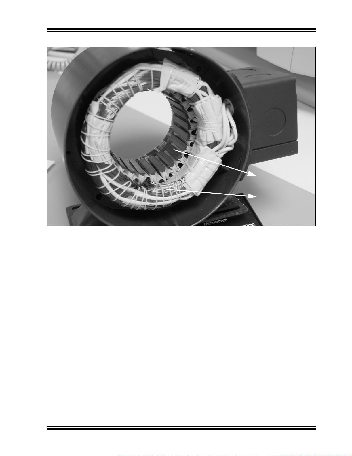
Stator
The stator of a BLDC motor consists of stacked steel
laminations with windings placed in the slots that are
axially cut along the inner periphery (as shown in
Figure 3). Traditionally, the stator resembles that of an
induction motor; however, the windings are distributed
in a different manner. Most BLDC motors have three
stator windings connected in star fashion. Each of
these windings are constructed with numerous coils
interconnected to form a winding. One or more coils are
placed in the slots and they are interconnected to make
a winding. Each of these windings are distributed over
the stator periphery to form an even numbers of poles.
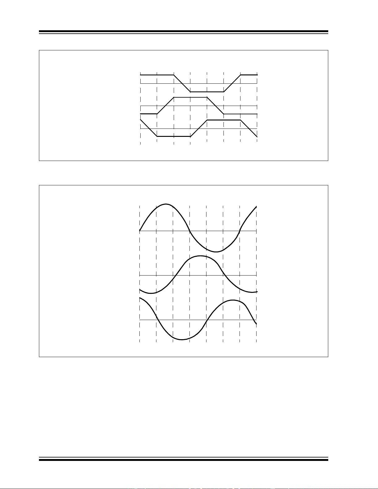
There are two types of stator windings variants:
trapezoidal and sinusoidal motors. This differentiation
is made on the basis of the interconnection of coils in
the stator windings to give the different types of back
Electromotive Force (EMF). Refer to the “What is
Back EMF?” section for more information.
As their names indicate, the trapezoidal motor gives a
back EMF in trapezoidal fashion and the sinusoidal
motor’s back EMF is sinusoidal, as shown in Figure 1
and Figure 2. In addition to the back EMF, the phase
current also has trapezoidal and sinusoidal variations
in the respective types of motor. This makes the torque
output by a sinusoidal motor smoother than that of a
trapezoidal motor. However, this comes with an extra
cost, as the sinusoidal motors take extra winding
interconnections because of the coils distribution on
the stator periphery, thereby increasing the copper
intake by the stator windings.
Depending upon the control power supply capability,
the motor with the correct voltage rating of the stator
can be chosen. Forty-eight volts, or less voltage rated
motors are used in automotive, robotics, small arm
movements and so on. Motors with 100 volts, or higher
ratings, are used in appliances, automation and in
industrial applications.
Author: Padmaraja Yedamale
Microchip Technology Inc.
Brushless DC (BLDC) Motor Fundamentals
剩余19页未读,继续阅读
资源评论


