没有合适的资源?快使用搜索试试~ 我知道了~
城市生活垃圾填埋场垂直井渗滤液流动的双孔隙模型解析解
0 下载量 49 浏览量
2024-05-23
14:14:33
上传
评论
收藏 1.4MB PDF 举报
温馨提示
![preview](https://dl-preview.csdnimg.cn/89345900/0001-e0a34926537ad4e00983470e0c04fcf9_thumbnail.jpeg)
![preview-icon](https://csdnimg.cn/release/downloadcmsfe/public/img/scale.ab9e0183.png)
试读
14页
城市生活垃圾填埋场垂直井渗滤液流动的双孔隙模型解析解
资源推荐
资源详情
资源评论
![pdf](https://img-home.csdnimg.cn/images/20210720083512.png)
![doc](https://img-home.csdnimg.cn/images/20210720083327.png)
![pdf](https://img-home.csdnimg.cn/images/20210720083512.png)
![docx](https://img-home.csdnimg.cn/images/20210720083331.png)
![application/pdf](https://img-home.csdnimg.cn/images/20210720083512.png)
![rar](https://img-home.csdnimg.cn/images/20210720083606.png)
![zip](https://img-home.csdnimg.cn/images/20210720083736.png)
![7z](https://img-home.csdnimg.cn/images/20210720083312.png)
![zip](https://img-home.csdnimg.cn/images/20210720083736.png)
![pdf](https://img-home.csdnimg.cn/images/20210720083512.png)
![zip](https://img-home.csdnimg.cn/images/20210720083736.png)
![rplib](https://img-home.csdnimg.cn/images/20210720083646.png)
![](https://csdnimg.cn/release/download_crawler_static/89345900/bg1.jpg)
Contents lists available at ScienceDirect
Engineering Geology
journal homepage: www.elsevier.com/locate/enggeo
Analytical solution of leachate flow to vertical wells in municipal solid waste
landfills using a dual-porosity model
Han Ke
a
, Jie Hu
a
, Xiao Bing Xu
b,
⁎
, Xiao Wen Wu
c
, Yu Chao Li
a
, Ji Wu Lan
a
a
Yuhangtang Road 866#, MOE Key Laboratory of Soft Soils and Geoenvironmental Engineering, Institute of Geotechnical Engineering, Zhejiang University, Hangzhou
310058, China
b
Liuhe Road 288#, Institute of Geotechnical Engineering, Zhejiang University of Technology, Hangzhou 310023, China
c
Gujiafan Road 22#, Hangzhou Urban & Rural Construction Design Institute Co., Ltd, 310004, China
ARTICLE INFO
Keywords:
MSW
Landfill
Leachate
Vertical well
Dual-porosity
Drawdown
ABSTRACT
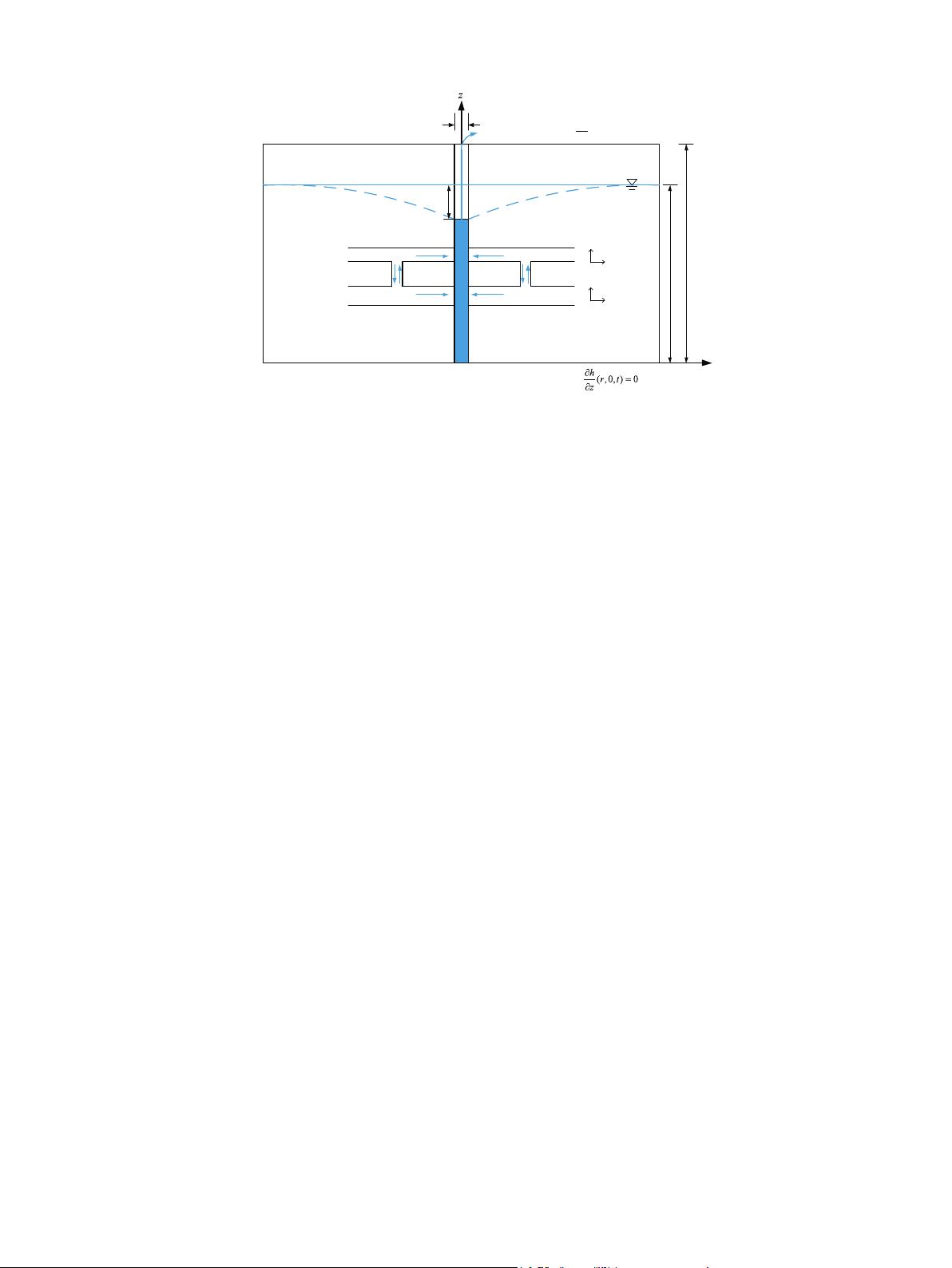
In this study, a flow model of leachate to vertical wells in municipal solid waste (MSW) landfills has been
established using a dual-porosity model. The proposed model divides waste into fracture and matrix domains,
the leachate in these two domains flows horizontally and vertically into a vertical well together, and mass
exchange occurs between them. An analytical solution of leachate drawdown under vertical wells pumping at a
constant rate is obtained through Laplace integral transformation and Separation of variables method. A sen-
sitivity analysis indicates that the hydraulic characteristics of the fracture domain (i.e., k
fr
and μ
sf
) have greater
influence on leachate drawdown than that of the matrix domain (i.e., k
mr
and μ
sm
). As the proportion of the
fracture domain within the total domain, w
f
, increases, additional large pores are available for leachate flow, and
leachate drawdown gradually decreased. As the anisotropy of hydraulic conductivity, k
r
/k
z
, increases, it becomes
increasingly difficult for leachate to flow downward, and leachate drawdown gradually decreases. A case study
of vertical well pumping tests at the Chang'an and Liming landfills indicated that the proposed model performed
better than the Theis model in leachate drawdown estimation. The values of w
f
and k
fr
/k
mr
were set to be 0.45
and 500 for the MSW in the Chang'an and Liming landfills, respectively.
1. Introduction
Landfilling remains one of the main municipal solid waste (MSW)
disposal methods worldwide. In the process of landfilling, a large
amount of leachate is produced because of rainfall infiltration and
waste degradation. Leachate production due to waste degradation de-
pends on the composition and the water content of MSW. MSW in de-
veloping countries, such as China, is significantly different from that in
developed countries, such as the United States. Fresh Chinese MSW has
a much higher food waste content (> 60%, kg/kg, wet basis) and initial
water content (40–60%, kg/kg, wet basis) compared to fresh MSW in
the United States. This is the main reason causing the much higher
leachate production ratio (51%, kg/kg, wet basis) at Chinese landfills
(Zhan et al., 2015). Because of the low hydraulic conductivity (ap-
proximately 1 × 10
−8
m/s) of waste in deep layers, and the gradual
clogging of leachate drainage systems, leachate cannot be effectively
removed from Chinese landfills ( Zhan et al., 2015). Therefore, a high
leachate level is gradually formed in Chinese landfills. The survey re-
sults in technical code CJJ176-2012 (MOHURD, 2012) indicated that
the ratio of leachate level to waste thickness (i.e., h/H) could reach 0.8
at Chinese landfills. The development of a high leachate level could
cause serious engineering problems, including (i) increasing the risk of
leachate leakage into the surrounding ground and water ( Rowe, 1998;
Cox et al., 2006; Xie et al., 2010), (ii) reducing landfill gas recovery
efficiency (Fadel et al., 1997; Townsend et al., 2005; Zhan et al., 2015),
and (iii) decreasing the factor of safety against slope stability (Koerner
and Soong, 2000; Blight, 2008; Zhan et al., 2008).
To ensure that landfills can be safely operated, high leachate levels
should be lowered. Vertical wells are conventionally used as a con-
tingency or long-term solution because of their construction con-
venience and good performance (Oweis et al., 1990; Wang et al., 2013;
Wu et al., 2015; Zhan et al., 2015; Slimani et al., 2017). To understand
the flow process of leachate to vertical wells, and to evaluate the lea-
chate drawdown around vertical wells, several numerical models have
been proposed by previous researchers (Rowe and Nadarajah, 1996; Al-
Thani et al., 2004; Olivier et al., 2009; McDougall, 2007; Hettiarachchi
et al., 2009; Feng et al., 2015; Slimani et al., 2017). Rowe and
Nadarajah (1996) established the governing equations for leachate flow
to vertical wells under steady-state conditions, and the finite element
method was used to solve them. Their analyses indicated that the
https://doi.org/10.1016/j.enggeo.2018.03.016
Received 20 October 2017; Received in revised form 14 March 2018; Accepted 18 March 2018
⁎
Corresponding author.
E-mail addresses: hujie1993@zju.edu.cn (J. Hu), xiaobingxu@zjut.edu.cn (X.B. Xu), liyuchao@zju.edu.cn (Y.C. Li), lanjiwu@zju.edu.cn (J.W. Lan).
Engineering Geology 239 (2018) 27–40
Available online 23 March 2018
0013-7952/ © 2018 Elsevier B.V. All rights reserved.
T
![](https://csdnimg.cn/release/download_crawler_static/89345900/bg2.jpg)
leachate level was a function of the radius of the wells, r
w
, the spacing
of the wells, 2R, the rainfall percolation rate, q
0
, and the horizontal
hydraulic conductivity of the waste, k
h
. They pointed out that the
vertical hydraulic conductivity of the waste, k
v
, also had a significant
influence on the leachate level around the vertical wells when the ratio
of q
0
to k
v
was > 0.2. Al-Thani et al. (2004) expanded their study to
include transient-state conditions, and the MODFLOW-SURFACT nu-
merical model was used to investigate transient leachate drawdown.
They found that the seepage face developed at the entry into the well,
so the leachate drawdown in the surrounding waste would not be as
significant as expected. In a field pumping test, Olivier et al. (2009)
used the classical Theis and Cooper-Jacob methods (Cooper and Jacob,
1946) to obtain average values of hydraulic conductivity and the sto-
rage coefficient of the waste. Then, MODFLOW-SURFACT was used to
simulate vertical wells pumping activity in complex 3D landfill cells.
Several researchers proposed models based on the Richards equation to
analyse leachate pumping and recirculation using vertical wells in
landfills (McDougall, 2007; Hettiarachchi et al., 2009; Feng et al., 2015;
Slimani et al., 2017). For example, Slimani et al. (2017) presented an
analysis of field leachate pumping and injection tests. When the
pumping stopped at 70 h, the leachate level in the pumping well in-
creased from 3.2 m at 70 h to 5.6 m at 90 h. The simulated leachate
level using the Richards model was 6.8 m at 90 h, which was much
higher than the measured value. They found that the significant dif-
ference between the simulated and measured leachate level during the
pumping and leachate level recovery phases might be due to the lim-
itation of Richards model, which neglected the double porosity effects
of the waste.
MSW is composed of different waste components which are re-
sponsible for the heterogeneous nature of the waste body. MSW has a
large range of pore size distributions, and leachate transport in landfills
is found to be dominated by the preferential flow (Rosqvist et al., 2005;
Woodman, 2007). Rosqvist et al. (2005) performed chloride tracer tests
to study water flow and solute transport through preferential flow paths
in waste. The experimental break-through curves (BTCs) suggested that
between 19% and 41% of the total water content participated in the
transport of solute through preferential flow paths. To describe such
preferential flow in waste, the dual-porosity model was established
(Gerke and van Genuchten, 1993; Fellner and Brunner, 2010; Pan et al.,
2010; Han et al., 2011). The dual-porosity model assumed that a waste
body could be divided into fracture and matrix domains, and the hy-
draulic conductivity of the fracture domain was much higher than that
of the matrix domain. In the model, leachate could flow through each
domain separately as well as between the two domains. Multi-step
outflow experiments were carried out by
Han et al. (2011) to assess
alternative conceptual models of pore structure in waste. After 1300 h
outflowing, the water pressure head at the top of the waste column, A1,
was measured to be −644 cm. The calculated water pressure head
using the dual-porosity model was −625 cm, while it reached up to
−378 cm when using a single-porosity model. The results showed that
the dual-porosity model performed significantly better than the single-
porosity model when describing leachate movement.
To calculate the transient drawdown around vertical wells in soils,
three types of analytical solutions were gradually developed: (i) the
Theis model (Theis, 1935), which assumed the aquifer was homo-
geneous and isotropic; (ii) the Boulton model (Boulton, 1954), which
considered drainage hysteresis (i.e., water could not be discharged
immediately under gravity during pumping) and was suitable for fine
grained soil aquifer; and (iii) the Neuman model (Neuman, 1972),
which considered both horizontal and vertical flow to vertical wells and
was suitable for anisotropic aquifer. These three models could not
consider preferential flow, and might not be suitable for analysing
leachate flow in MSW landfills. Based on the previous studies men-
tioned above, an analytical solution for leachate flow to vertical wells in
MSW landfills is required to consider preferential flow in waste.
In this study, a model of leachate flow to vertical wells in MSW
landfills was established based on the dual-porosity model of Gerke and
van Genuchten (1993). The model considered both horizontal and
vertical leachate flow to vertical wells. An analytical solution of lea-
chate drawdown under vertical well pumping at a constant rate was
obtained through Laplace integral transformation and Separation of
variables method. Then, a sensitivity analysis was conducted to in-
vestigate the effect of the hydraulic conductivity of the fracture and
matrix domains (i.e., k
fr
and k
mr
), the proportion of fracture domain in
total domain (i.e., w
f
), the specific storage of fracture and matrix do-
mains (i.e., μ
sf
and μ
sm
), and the anisotropy of hydraulic conductivity
(i.e., k
r
/k
z
) on leachate drawdown. In addition, suggestions to achieve
leachate drawdown using vertical wells in landfills were also presented.
Finally, the values of model parameters suitable for Chinese landfills
were determined through analysis of the field pumping tests in the
Chang'an and Liming landfills.
2. Mathematical model
The mathematical model is established in a radial cylindrical system
(see Fig. 1). The radial cylindrical system includes a radial coordinate,
r, and a vertical coordinate, z. Here, the vertical well (radius r
w
) is lo-
cated in the centre of the system, and leachate is pumped at a constant
rate of Q. The thickness of the waste body and initial leachate level are
H and h
0
, respectively.
2r
w
r
s
h
0
HMatrix flow
Fracture flow
Matrix flow
Fracture flow
Mass exchange
Initial leachate level
Leachate level after pumping
k
mz
k
mr
k
fz
k
fr
MSW
Landfill cap
Bottom of landfill
Infinite
Boundary:
Vertical well
(, ,) 0
h
rHt
z
∂
=
∂
0
(,,)hzth−∞ =
Q
Impervious:
Impervious:
Infinite
Boundary:
0
(,,)hzth+∞ =
A
C
B
Fig. 1. Flow model of leachate to vertical well in MSW landfill.
H. Ke et al.
Engineering Geology 239 (2018) 27–40
28
![](https://csdnimg.cn/release/download_crawler_static/89345900/bg3.jpg)
Based on the dual-porosity model proposed by Gerke and van
Genuchten (1993), pores in MSW are divided into fracture and matrix
domains. The leachate flow in the fracture and matrix domains are both
considered to be anisotropic. Firstly, the leachate level in the vertical
well would decrease during pumping at a constant rate of Q. Then, the
leachate in the fracture and matrix domains would flow to the well
under the hydraulic gradient. Leachate mass exchange between the two
domains would occur during this process. Thus, the leachate level in the
surrounding waste body would decrease correspondingly, and a funnel
of leachate level drawdown (i.e., AC and BC in Fig. 1) was formed. As
the horizontal distance from the well increases, the hydraulic gradient
decreases gradually. The position where the leachate drawdown is zero
(i.e., A and B in Fig. 1) corresponds to the influence radius of the well.
In the physical model describing the leachate drawdown process, all
the assumptions made are as follows:
(1) Leachate flow occurs in directions parallel to the horizontal axis, r,
and the vertical axis, z,inFig. 1 (Neuman, 1972).
(2) Leachate in the fracture and matrix domains flows to the well to-
gether, leachate mass exchange occurs between the two domains
(Gerke and van Genuchten, 1993), and the anisotropy values of the
hydraulic conductivity are the same in the two domains.
(3) At time t = 0, the leachate level in MSW is equivalent to the initial
leachate level, h
0
.
(4) The well is located in the closed area of the landfill with a final
cover, and there is no rainfall infiltration at the surface. Thus, the
top and bottom boundaries are set as impervious.
(5) The influence radius of the well has a limited value. The left and
right boundaries are set as infinite boundaries with a stable leachate
level of h
0
.
(6) Pumping in the well is operated at a constant rate of Q, and the flux
is uniformly distributed along the depth of the well (Theis, 1935).
(7) Leachate flow obeys Darcy's law.
(8) The particle size of MSW is relatively larger than fine-grained soil,
and the drainage hysteresis is neglected in landfills.
(9) The leachate drawdown, s, is much less than the initial leachate
level, h
0
, and the decreasing hydraulic conductivity of waste with
depth is not considered for simplicity.
The governing differential equations of leachate flow to the well are
as follows:
For the fracture domain, the governing equation (i.e., Eq. (1))is
established according to the principle of leachate balance under as-
sumptions (1) and (2). The first and second items on the left side of Eq.
(1) represent the horizontal and vertical flux into the domain, respec-
tively. The third item on the left side of Eq. (1) represents the leachate
mass exchange between fracture and matrix domains. The item on the
right side of Eq. (1) represents the net change of leachate mass in the
domain.
⎜⎟
⎛
⎝
∂
∂
+
∂
∂
⎞
⎠
+
∂
∂
+−=
∂
∂
k
h
rr
h
r
k
h
z
αk h h μ
h
t
1
()
fr
ff
fz
f
mm f
sf
f2
2
2
2
(1)
where h
f
(m) and h
m
(m) are the hydraulic head of the fracture and
matrix domains, respectively. k
fr
(m/s) and k
fz
(m/s) are the horizontal
and vertical hydraulic conductivity of the fracture domain, respectively.
k
m
(m/s) is the hydraulic conductivity at the interface between the
fracture and matrix domains. μ
sf
(m
−1
) is the specific storage of the
fracture domain and represents the volume of water released from a
unit volume porous medium with a unit drop of hydraulic head. α
(m
−2
) is the coefficient of leachate mass exchange between the two
domains and can be expressed as α = βδ/a
2
(Gerke and van Genuchten,
1993), β is a shape factor that is dependent on the geometry of porous
medium, δ is an empirical scaling factor, and a (m) is the distance from
the centre of the matrix to the fracture boundary. r (m) is the radial
distance from the well, z (m) is the vertical distance from the landfill
bottom, and t (s) is the pumping time.
For the matrix domain, the governing equation (i.e., Eq. (2))is
derived in a manner similar to Eq. (1).
⎛
⎝
∂
∂
+
∂
∂
⎞
⎠
+
∂
∂
−−=
∂
∂
k
h
rr
h
r
k
h
z
αk h h μ
h
t
1
()
mr
mm
mz
m
mm f
sm
m2
2
2
2
(2)
where k
mr
(m/s) and k
mz
(m/s) are the horizontal and vertical hydraulic
conductivity of the matrix domain, respectively, and μ
sm
(m
−1
) is the
specific storage of the matrix domain.
According to assumption (3), the initial hydraulic head can be ex-
pressed as follows:
⎧
⎨
⎩
==
==
=
=
hrzt hrz h
hrzt hrz h
(, ,)| (, ,0)
(, ,)| (, ,0)
ftf
mtm
00
00
(3)
According to assumption (4), the top and bottom boundaries are
impervious. In other words, the hydraulic gradient is equal to zero.
∂
∂
=
∂
∂
=
hrHt
z
hrHt
z
(, , )
(, , )
0
f
m
(4)
∂
∂
=
∂
∂
=
hr t
z
hr t
z
(,0,)
(,0,)
0
f
m
(5)
According to assumption (5), the left and right sides are infinite
boundaries. In other words, the hydraulic head has a constant value of
h
0
.
±∞ = ±∞ =hzth zth(,,) (,,)
fm0
(6)
According to assumptions (6) and (7), leachate is pumped at a
constant rate of Q, and the flux is uniformly distributed along the depth
of the well. Using Darcy's law, the boundary condition at the wellbore
can be expressed as:
=
∂
∂
+
∂
∂
→
Q
πrh
k
h
r
k
h
r
r
2
(0)
fr
f
mr
m
0
(7)
where Q (m
3
/s) is the leachate pumping rate.
The hydraulic head, h
f
and h
m
, are determined by the governing
equations of the two domains (i.e., Eqs. (1)–(2)), the initial condition
(i.e., Eq. (3)), and the boundary conditions (Eqs. (4)–(7)). This indicates
that h
f
and h
m
are related to the hydraulic conductivity of waste (i.e., k
fr
,
k
fz
, k
mr
, k
mz
, k
m
), the specific storage of waste (i.e., μ
sf
, μ
sm
), leachate
mass exchange parameters (i.e., α, k
m
), initial leachate level (i.e., h
0
),
and leachate pumping rate (i.e., Q). The solutions of h
f
and h
m
are
shown in the following section.
3. Solution to the model
All the dimensionless definitions of the variables in Eqs. (1)–(7) are
shown in Appendix A. The dimensionless mathematical model is de-
fined as follows:
For the fracture domain:
⎜⎟
⎛
⎝
∂
∂
+
∂
∂
+
∂
∂
⎞
⎠
+−=
∂
∂
k
h
rr
h
rh
h
z
λhhμ
h
t
11
()
fD
DD
fD
DD
fD
D
mf mD fD
f
fD
D
2
2
2
2
(8)
For the matrix domain:
⎜⎟
−
⎛
⎝
∂
∂
+
∂
∂
+
∂
∂
⎞
⎠
−−
=
∂
∂
k
h
rr
h
rh
h
z
λh h
μ
h
t
(1 )
11
()
mD
DD
mD
DD
mD
D
mf mD fD
m
mD
D
2
2
2
2
(9)
Initial condition:
==hrz h rz(, ,0) (, ,0) 0
fDDD mDDD
(10)
Impervious top and bottom boundary conditions:
H. Ke et al.
Engineering Geology 239 (2018) 27–40
29
剩余13页未读,继续阅读
资源评论
![avatar-default](https://csdnimg.cn/release/downloadcmsfe/public/img/lazyLogo2.1882d7f4.png)
![avatar](https://profile-avatar.csdnimg.cn/cb870bbdd7a340338b08a4ccf0175330_weixin_44259522.jpg!1)
___Y1
- 粉丝: 5148
- 资源: 160
上传资源 快速赚钱
我的内容管理 展开
我的资源 快来上传第一个资源
我的收益
登录查看自己的收益我的积分 登录查看自己的积分
我的C币 登录后查看C币余额
我的收藏
我的下载
下载帮助
![voice](https://csdnimg.cn/release/downloadcmsfe/public/img/voice.245cc511.png)
![center-task](https://csdnimg.cn/release/downloadcmsfe/public/img/center-task.c2eda91a.png)
安全验证
文档复制为VIP权益,开通VIP直接复制
![dialog-icon](https://csdnimg.cn/release/downloadcmsfe/public/img/green-success.6a4acb44.png)