ORDER NO.
PIONEER CORPORATION 1-1, Shin-ogura, Saiwai-ku, Kawasaki-shi, Kanagawa 212-0031, Japan
PIONEER ELECTRONICS (USA) INC. P.O. Box 1760, Long Beach, CA 90801-1760, U.S.A.
PIONEER EUROPE NV Haven 1087, Keetberglaan 1, 9120 Melsele, Belgium
PIONEER ELECTRONICS ASIACENTRE PTE. LTD. 253 Alexandra Road, #04-01, Singapore 159936
PIONEER CORPORATION
2011
2011 Printed in Japan
VSX-1021-K
RRV4176
AUDIO/VIDEO MULTI-CHANNEL RECEIVER
VSX-1021-K
THIS MANUAL IS APPLICABLE TO THE FOLLOWING MODEL(S) AND TYPE(S).
Model Type Power Requirement Remarks
VSX-1021-K UXCNCB AC 120 V
K-IZV JUNE
2
VSX-1021-K
1
2 3 4
A
B
C
D
E
F
1
2 3 4
SAFETY INFORMATION
WARNING
This product may contain a chemical known to the State of California to cause cancer, or birth defects or other reproductive
harm.
Health & Safety Code Section 25249.6 - Proposition 65
This service manual is intended for qualified service technicians; it is not meant for the casual do-it-
yourselfer. Qualified technicians have the necessary test equipment and tools, and have been trained
to properly and safely repair complex products such as those covered by this manual.
Improperly performed repairs can adversely affect the safety and reliability of the product and may
void the warranty. If you are not qualified to perform the repair of this product properly and safely, you
should not risk trying to do so and refer the repair to a qualified service technician.
1. SAFETY PRECAUTIONS
The following check should be performed for the
continued protection of the customer and service
technician.
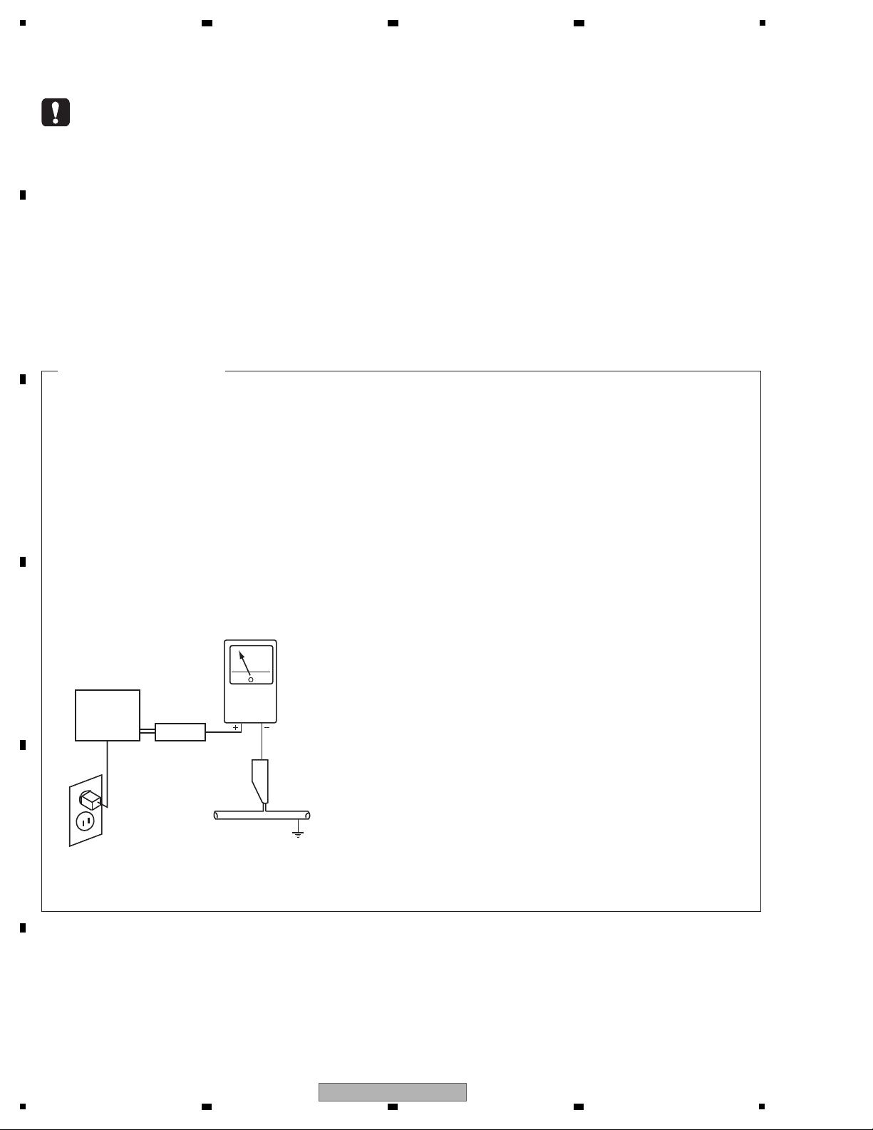
LEAKAGE CURRENT CHECK
Measure leakage current to a known earth ground
(water pipe, conduit, etc.) by connecting a leakage
current tester such as Simpson Model 229-2 or
equivalent between the earth ground and all exposed
metal parts of the appliance (input/output terminals,
screwheads, metal overlays, control shaft, etc.). Plug
the AC line cord of the appliance directly into a 120 V
AC 60 Hz outlet and turn the AC power switch on. Any
current measured must not exceed 0.5 mA.
ANY MEASUREMENTS NOT WITHIN THE LIMITS
OUTLINED ABOVE ARE INDICATIVE OF A POTENTIAL
SHOCK HAZARD AND MUST BE CORRECTED BEFORE
RETURNING THE APPLIANCE TO THE CUSTOMER.
2. PRODUCT SAFETY NOTICE
Many electrical and mechanical parts in the appliance
have special safety related characteristics. These are
often not evident from visual inspection nor the protection
afforded by them necessarily can be obtained by using
replacement components rated for voltage, wattage, etc.
Replacement parts which have these special safety
characteristics are identified in this Service Manual.
Electrical components having such features are
identified by marking with a > on the schematics and on
the parts list in this Service Manual.
The use of a substitute replacement component which
does not have the same safety characteristics as the
PIONEER recommended replacement one, shown in the
parts list in this Service Manual, may create shock, fire,
or other hazards.
Product Safety is continuously under review and new
instructions are issued from time to time. For the latest
information, always consult the current PIONEER Service
Manual. A subscription to, or additional copies of,
PIONEER Service Manual may be obtained at a nominal
charge from PIONEER.
Leakage
current
tester
Reading should
not be above
0.5 mA
Device
under
test
Test all
exposed metal
surfaces
Also test with
plug reversed
(Using AC adapter
plug as required)
Earth
ground
AC Leakage Test
(FOR USA MODEL ONLY)

3
VSX-1021-K
5
6 7 8
5
6 7 8
A
B
C
D
E
F
CONTENTS
SAFETY INFORMATION.......................................................................................................................................................... 2
1. SERVICE PRECAUTIONS.................................................................................................................................................... 4
1.1 NOTES ON SOLDERING ............................................................................................................................................... 4
1.2 NOTES ON REPLACING PARTS ................................................................................................................................... 4
1.3 SERVICE NOTICE.......................................................................................................................................................... 4
2. SPECIFICATIONS................................................................................................................................................................. 5
3. BASIC ITEMS FOR SERVICE .............................................................................................................................................. 6
3.1 CHECK POINTS AFTER SERVICING ........................................................................................................................... 6
3.2 JIGS LIST ....................................................................................................................................................................... 6
3.3 PCB LOCATIONS ........................................................................................................................................................... 7
4. BLOCK DIAGRAM .............................................................................................................................................................. 10
4.1 OVERALL WIRING DIAGRAM ..................................................................................................................................... 10
4.2 AUDIO BLOCK DIAGRAM............................................................................................................................................ 12
4.3 VIDEO BLOCK DIAGRAM............................................................................................................................................ 14
4.4 D-MAIN BLOCK DIAGRAM .......................................................................................................................................... 16
4.5 D-MAIN VIDEO BLOCK DIAGRAM .............................................................................................................................. 18
4.6 GND BLOCK DIAGRAM ............................................................................................................................................... 20
5. DIAGNOSIS ........................................................................................................................................................................ 22
5.1 DIAGNOSIS FLAWCHART........................................................................................................................................... 22
5.2 ERROR INDICATIONS ................................................................................................................................................. 31
5.3 DETECTION CIRCUIT ................................................................................................................................................. 32
6. SERVICE MODE................................................................................................................................................................. 34
6.1 TEST MODE................................................................................................................................................................. 34
6.2 DEFAULT SETTINGS ................................................................................................................................................... 36
7. DISASSEMBLY ................................................................................................................................................................... 37
8. EACH SETTING AND ADJUSTMENT ................................................................................................................................ 47
8.1 ADJUSTMENT REQUIRED WHEN THE UNIT IS REPAIRED OR REPLACED .......................................................... 47
8.2 USB BACKUP............................................................................................................................................................... 48
8.3 UPDATING OF THE FIRMWARE ................................................................................................................................. 50
8.4 IDLE CURRENT ADJUSTMENT .................................................................................................................................. 53
9. EXPLODED VIEWS AND PARTS LIST............................................................................................................................... 54
9.1 PACKING SECTION ..................................................................................................................................................... 54
9.2 EXTERIOR SECTION .................................................................................................................................................. 56
10. SCHEMATIC DIAGRAM.................................................................................................................................................... 60
10.1 AUDIO ASSY .............................................................................................................................................................. 60
10.2 A
MP7 ASSY (1/2) ....................................................................................................................................................... 62
10.3 AMP7 ASSY (2/2) ....................................................................................................................................................... 64
10.4 MAIN ASSY ................................................................................................................................................................ 66
10.5 SW, HP, MIC, G-L, G-R, WG-A and WG-B ASSYS .................................................................................................... 68
10.6 VIDEO ASSY .............................................................................................................................................................. 70
10.7 F-V, FRONT and POWER ASSYS.............................................................................................................................. 72
10.8 IR ASSY...................................................................................................................................................................... 74
10.9 SMPS ASSY............................................................................................................................................................... 76
10.10 BR ASSY .................................................................................................................................................................. 78
10.11 D-MAIN ASSY (1/9) .................................................................................................................................................. 80
10.12 D-MAIN ASSY (2/9) .................................................................................................................................................. 82
10.13 D-MAIN ASSY (3/9) .................................................................................................................................................. 84
10.14 D-MAIN ASSY (4/9) .................................................................................................................................................. 86
10.15 D-MAIN ASSY
(5/9) .................................................................................................................................................. 88
10.16 D-MAIN ASSY (6/9) .................................................................................................................................................. 90
10.17 D-MAIN ASSY (7/9) .................................................................................................................................................. 92
10.18 D-MAIN ASSY (8/9) .................................................................................................................................................. 94
10.19 D-MAIN ASSY (9/9) .................................................................................................................................................. 96
10.20 F-USB and BT ASSYS ............................................................................................................................................. 98
11. PCB CONNECTION DIAGRAM ...................................................................................................................................... 100
11.1 AUDIO ASSY ............................................................................................................................................................ 100
11.2 AMP7 ASSY ............................................................................................................................................................. 102
11.3 MAIN ASSY .............................................................................................................................................................. 104
11.4 SW, HP and MIC ASSYS.......................................................................................................................................... 108
11.5 G-L, G-R, WG-A and WG-B ASSYS......................................................................................................................... 109
11.6 VIDEO ASSY ............................................................................................................................................................ 110
11.7 F-V
, FRONT and POWER ASSYS............................................................................................................................ 112
11.8 IR ASSY.................................................................................................................................................................... 116
11.9 SMPS ASSY............................................................................................................................................................. 118
11.10 BR and CCG ASSYS.............................................................................................................................................. 120
11.11 D-MAIN ASSY ........................................................................................................................................................ 122
11.12 F-USB and BT ASSYS ........................................................................................................................................... 126
12. PCB PARTS LIST............................................................................................................................................................ 127
4
VSX-1021-K
1
2 3 4
A
B
C
D
E
F
1
2 3 4
1. SERVICE PRECAUTIONS
1.1 NOTES ON SOLDERING
1.2 NOTES ON REPLACING PARTS
1.3 SERVICE NOTICE
• For environmental protection, lead-free solder is used on the printed circuit boards mounted in this unit.
Be sure to use lead-free solder and a soldering iron that can meet specifications for use with lead-free solders for repairs
accompanied by reworking of soldering.
• Compared with conventional eutectic solders, lead-free solders have higher melting points, by approximately 40 ºC.
Therefore, for lead-free soldering, the tip temperature of a soldering iron must be set to around 373 ºC in general, although
the temperature depends on the heat capacity of the PC board on which reworking is required and the weight of the tip of
the soldering iron.
Do NOT use a soldering iron whose tip temperature cannot be controlled.
Compared with eutectic solders, lead-free solders have higher bond strengths but slower wetting times and higher melting
temperatures (hard to melt/easy to harden).
The following lead-free solders are available as service parts:
• Parts numbers of lead-free solder:
GYP1006 1.0 in dia.
GYP1007 0.6 in dia.
GYP1008 0.3 in dia.
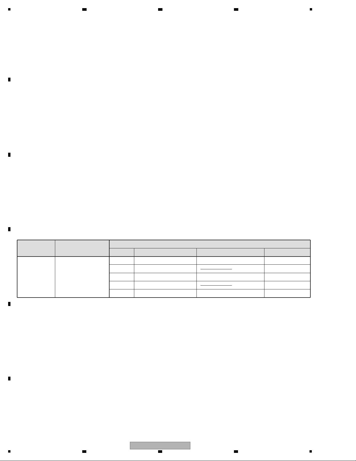
The part listed below is difficult to replace as a discrete component part.
When the part listed in the table is defective, replace whole Assy.
EMMA2RL2 UPD61283F1-407LU2A BGA
IC903 HDMI Receiver IC with heat-pad
Assy Name
D-MAIN Assy
IC101
7028070351010-IL
PCB Assy Part No.
Ref No. Function Part No.
Parts that is Difficult to Replace
Remarks
IC9204 Media Processor IC DM860 BGA
IC1602 HDMI Transmitter IC with heat-pad
IC9002 Audio DSP System IC D810K013BZKB400 IC with heat-pad
• Discharging
For more detail, please refer to "7. DISASSEMBLY - 1. Discharging".
• Notes on Ground Points Connection
For more detail, please refer to "7. DISASSEMBLY - 2. Notes on Ground Points Connection".
5
VSX-1021-K
5
6 7 8
5
6 7 8
A
B
C
D
E
F
2. SPECIFICATIONS
Amplifier section
Continuous average power output of 90 watts* per channel,
min., at 8 ohms, from 20 Hz to 20 000 Hz with no more than
0.08 %** total harmonic distortion.
Front (stereo) ......................................... 90 W + 90 W
Power output (1 kHz, 8 Ω, 0.05 %, 1 ch driven)
................................................................120 W per channel
Guaranteed speaker impedance ........................ 6 Ω to 16 Ω
* Measured pursuant to the Federal Trade Commission’s
Trade Regulation rule on Power Output Claims for
Amplifiers
** Measured by Audio Spectrum Analyzer
Audio Section
Input (Sensitivity/Impedance)
LINE...........................................................315 mV/47 kΩ
Output (Level/Impedance)
REC..........................................................315 mV/2.2 kΩ
Signal-to-Noise Ratio (IHF, short circuited, A network)
LINE...................................................................... 100 dB
Signal-to-Noise Ratio [EIA, at 1 W (1 kHz)]
LINE........................................................................ 81 dB
Tuner Section
Frequency Range (FM) .....................87.5 MHz to 108 MHz
Antenna Input (FM)................................... 75 Ω unbalanced
Frequency Range (AM) ...................... 530 kHz to 1700 kHz
Antenna (AM) ...............................Loop antenna (balanced)
Video Section
Signal level
Composite Video ........................................ 1 Vp-p (75 Ω)
Component Video.............................. Y: 1.0 Vp-p (75 Ω),
PB/PR: 0.7 Vp-p (75 Ω)
Corresponding maximum resolution
Component Video.......1080p (1125p) (Video convert off)
Digital In/Out Section
HDMI terminal ........................................19-pin (Not DVI)
HDMI output type.......................................... 5 V, 100 mA
USB terminal .......................USB2.0 Full Speed (Type A)
iPod terminal.......................USB, and Video (Composite)
SIRIUS antenna cable..................... 8-pin mini DIN cable
ADAPTER PORT terminal ............................ 5 V, 100 mA
WIRELESS LAN ADAPTER terminal ........... 5 V, 600 mA
Integrated Control Section
Control (SR) terminal..................ø 3.5 Mini-jack (MONO)
Control (IR) terminal ...................ø 3.5 Mini-jack (MONO)
IR signal........................... High Active (High Level: 2.0 V)
Network Section
LAN terminal........................... 10 BASE-T/100 BASE-TX
Miscellaneous
Power requirements................................AC 120 V, 60 Hz
Power consumption ............................................... 550 W
In standby...............0.2 W (HDMI Setup – Control : OFF)
0.3 W (HDMI Setup – Control : ON)
Dimensions.. 435 mm (W) x 168 mm (H) x 362.5 mm (D)
(17 3/16 in. (W) x 6 5/8 in. (H) x 14 5/16 in. (D))
Weight (without package) .....................10 kg (22 lb 1 oz)
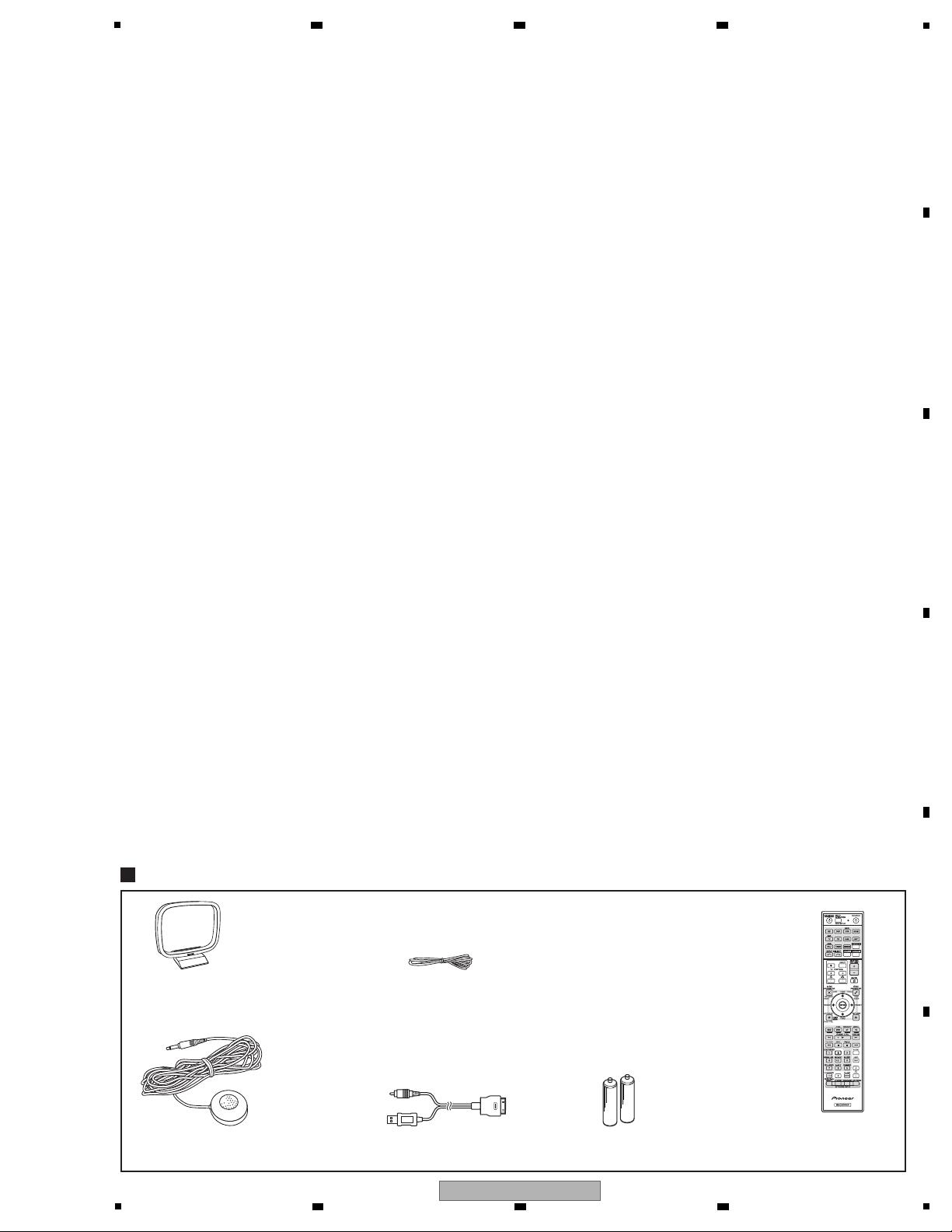
Number of Furnished Parts
MCACC Setup microphone .................................................1
Remote control unit .............................................................1
AAA size IEC R03 dry cell batteries ....................................2
iPod cable............................................................................1
AM loop antenna .................................................................1
FM wire antenna..................................................................1
CD-ROM (AVNavigator)
Operating instructions
Note
• Specifications and the design are subject to possible
modifications without notice, due to improvements.
iPod cable
(L308102013020-IL)
Accessories
Remote control unit
(AXD7615)
(8300761500010-IL)
AM loop antenna
(E601019000010-IL)
FM wire antenna
(E605010140010-IL)
Operating instructions
(5707000004890-IL)
CD-ROM (AVNavigator)
(6517000000120-IL)
AAA size IEC R03 dry cell batteries
(to confirm system operation) x2
Setup microphone (cable: 5 m (16.4 ft.))
(APM7008)