Application Note
AN042
CC2431 Location Engine
By K. Aamodt
1 KEYWORDS
• CC2430
• CC2431
• ZigBee
• Location Engine
2 INTRODUCTION
This document describes the location
engine implemented in the CC2431.
CC2431 is a ZigBee system on chip, so it
will be natural to use the location engine in
a ZigBee network. This manual is written
to be as general as possible and will not
describe any protocol specific
considerations.
The main purposes of this document it to
present some basic aspects of the location
technology, and provide some hints and
tips for easy developing of systems using
the CC2431 location engine. This
document should be read as an extension
to the CC2431 and CC2430 data sheets.
Application Note AN042 (Rev. 1.0)
SWRA095
Page 1 of 20

Application Note
AN042
Table of Contents
1 KEYWORDS ................................................................................................................... 1
2 INTRODUCTION............................................................................................................. 1
3 LOCATION ENGINE....................................................................................................... 3
3.1 NODE TYPES.............................................................................................................. 4
3.1.1 Reference node .................................................................................................................4
3.1.2 Blind Node........................................................................................................................4
3.2 THE LOCATION HARDWARE ......................................................................................... 4
3.2.1 Input..................................................................................................................................5
3.2.2 Output...............................................................................................................................5
4 RECEIVED SIGNAL STRENGTH INDICATOR (RSSI) ................................................. 6
4.1 OFFSET..................................................................................................................... 6
4.2 LINEARITY.................................................................................................................. 6
4.3 THEORETICAL SIGNAL PROPAGATION........................................................................... 7
4.4 RSSI – PRACTICAL CONSIDERATIONS ......................................................................... 7
4.4.1 Simple ways to filter the RSSI values................................................................................7
4.4.2 Calculated RSSI vs. measured RSSI.................................................................................8
5 DIFFERENT PARAMETERS – INFLUENCE................................................................. 9
5.1 A – RSSI VALUE MEASURED ONE METER FROM THE SENDER ...................................... 10
5.1.1 Measuring A ...................................................................................................................10
5.1.2 A versus calculated position...........................................................................................11
5.2 N – SIGNAL PROPAGATION COEFFICIENT ................................................................... 12
5.2.1 Measuring n....................................................................................................................13
5.3 NUMBER OF REFERENCE NODES ............................................................................... 14
6 SOFTWARE ALGORITHMS ........................................................................................ 15
6.1 SELECTION OF “BEST” REFERENCE NODES................................................................. 15
6.2 EXTENSION OF THE COVERED AREA........................................................................... 15
6.3 LEVEL/ FLOOR INDICATION ........................................................................................ 16
7 CONTROL SYSTEM/ CENTRAL ................................................................................. 18
8 GENERAL INFORMATION .......................................................................................... 19
8.1 DOCUMENT HISTORY................................................................................................ 19
9 IMPORTANT NOTICE .................................................................................................. 20
Application Note AN042 (Rev. 1.0)
SWRA095
Page 2 of 20
Application Note
AN042
3 LOCATION ENGINE
The location algorithm used in the CC2431 Location Engine is based on Received Signal
Strength Indicator (RSSI) values. The RSSI value will decrease when the distance increases.
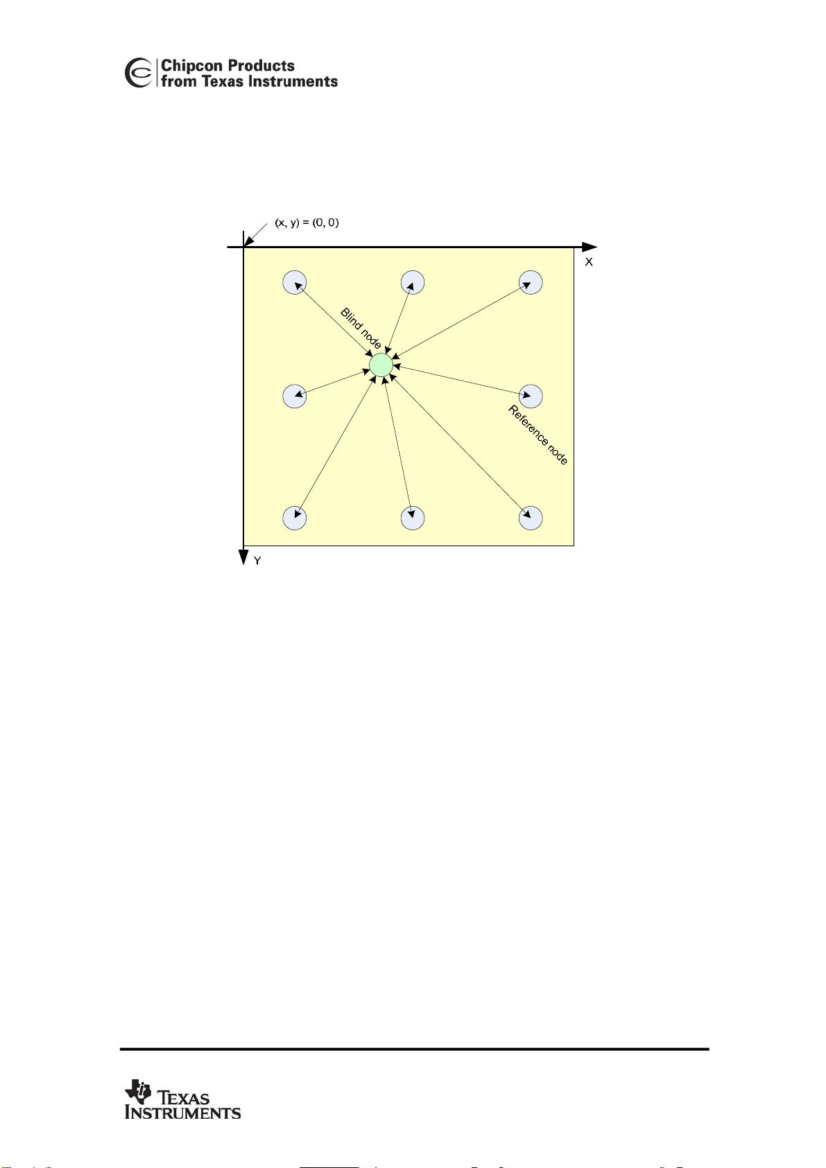
Figure 1: Location Estimation
Figure 1 shows a simplified system for location detection. “Reference node” is a static node
placed at a known position. For simplicity this node knows its own position and can tell other
nodes where it is on request. A reference node does not need to implement the hardware
needed for location detection, it will not perform any calculation at all. A “Blind node” is a node
built with CC2431. This node will collect signals from all reference nodes responding to a
request, read out the respective RSSI values, feed the collected values into the hardware
engine, and afterwards it reads out the calculated position and sends the position information
to a control application.
The minimum data contained in a packet sent from a reference node to a blind node shall be
the reference nodes’ X and Y parameters. The RSSI value is calculated by the receiver, i.e.
the blind node.
The main feature of the location engine is that the location calculation can be performed at
each blind node, hence the algorithm is decentralised. This property reduces the amount of
data transferred in the network, since only the calculated position is transferred, not the data
used to perform the calculation.
To map each location to a distinct place in the natural environment, a two dimensional grid is
used. The directions will, in the following, be denoted X and Y. In all the figures X is defined to
be the horizontal direction and Y the vertical. The CC2431 Location Engine can only handle
two dimensions, but it’s possible to handle a third dimension in software (i.e. to represent
floors in a building). The point named (X, Y) = (0, 0) is located in the upper left corner of the
grid.
Application Note AN042 (Rev. 1.0)
SWRA095
Page 3 of 20

Application Note
AN042
3.1 Node types
3.1.1 Reference node
A node which has a static location is called a reference node. This node must be configured
with X and Y value that correspond to the physical location.
The main task for a reference node is to provide a “reference” packet that contains X and Y
coordinates to the blind node, also referred to as an anchor node.
Since this node is not using the hardware location engine at all, it is not necessary to use a
CC2431 for the purpose. This means that a reference node can be run on either a CC2430 or
a CC2431. Since CC2430/31 is based on the same transceiver as CC2420, even a CC2420
together with a suitable microcontroller can be used as reference node.
3.1.2 Blind Node
A blind node will communicate with the closest reference nodes, collecting X, Y and RSSI for
each of these nodes, and calculate its position based on the parameter input using the
location engine hardware. Afterwards the calculated position should be sent to a control
station. This control station could be a PC or another node in the system.
A blind node must be using CC2431.
3.2 The location hardware
The location engine utilizes an extremely simple interface seen from the software layer; write
parameters in, wait for the calculation to performed, and read out the calculated position out.
This chapter will discuss the different parameters and how the shall be interpreted.
Figure 2: Location Engine, input and output
Application Note AN042 (Rev. 1.0)
SWRA095
Page 4 of 20
Application Note
AN042
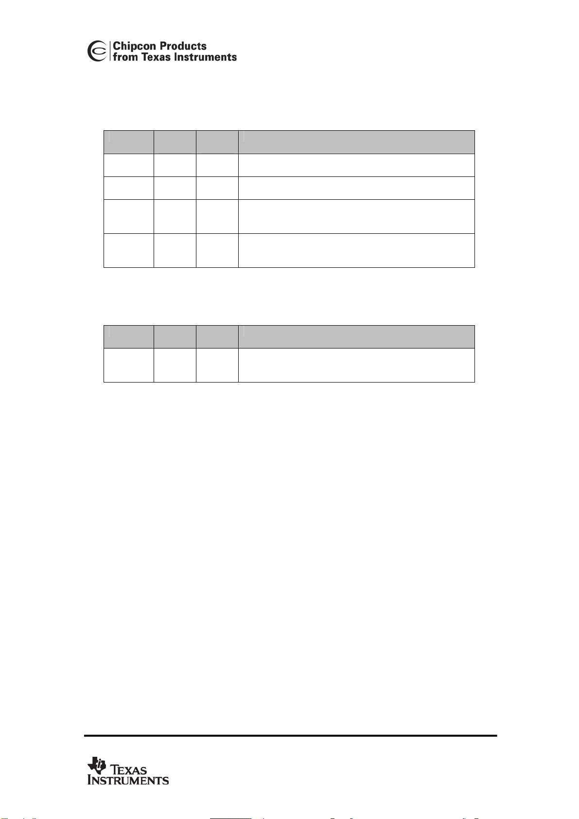
3.2.1 Input
Table 1 shows all necessary input to the location hardware. All the values will be described in
details later in this document. The following is a brief introduction.
Name Min.
value
Max.
value
Description
A 30 50
The absolute RSSI value in dBm one meter apart for
a transmitter.
n_index 0 31
This value represent the signal propagation
exponent, this value depends on the environment.
RSSI 40 95
Received Signal Strength Indicator this value is
measured in dBm. The location engine using the
absolute value as input.
X, Y 0 63.75
These values represent the X and Y coordinates
relative to a fixed point. The values are in meters
and the accuracy is 0.25 meters.
Table 1: Hardware inputs parameters
3.2.2 Output
Name Min.
value
Max.
value
Description
X, Y 0 63.5
These values represent the calculated X and Y
coordinates relatively to a fixed point. The values
are in meters.
Table 2: Location Engine Output
Application Note AN042 (Rev. 1.0)
SWRA095
Page 5 of 20