SL811HS
Cypress Semiconductor Corporation • 3901 North First Street • San Jose • CA 95134 • 408-943-2600
Document #: 38-08008 Rev. *A Revised March 14, 2002
SL811HS
Embedded USB Host/Slave Controller

SL811HS
Document #: 38-08008 Rev. *A Page 2 of 29
TABLE OF CONTENTS
1.0 CONVENTIONS ..............................................................................................................................4
2.0 DEFINITIONS ..................................................................................................................................4
3.0 REFERENCES ................................................................................................................................4
4.0 INTRODUCTION .............................................................................................................................4
4.1 Block Diagram ................................................................................................................................4
4.2 SL811HS Host or Slave Mode Selection [Master/Slave Mode] ..................................................5
4.3 Features ..........................................................................................................................................5
4.4 Data Port, Microprocessor Interface ............................................................................................6
4.5 Interrupt Controller ........................................................................................................................6
4.6 Buffer Memory ...............................................................................................................................6
4.7 PLL Clock Generator .....................................................................................................................6
4.8 USB Transceiver ............................................................................................................................8
5.0 SL811HS REGISTERS ...................................................................................................................8
5.1 Register Values on Power-up and Reset .....................................................................................9
5.2 USB Control Registers ..................................................................................................................9
5.3 SL811HS Control Registers ........................................................................................................12
6.0 SL811HS AND SL811HST-AC PHYSICAL CONNECTIONS ......................................................16
6.1 SL811HS Physical Connections .................................................................................................16
6.2 SL811HST-AC Physical Connections ........................................................................................19
7.0 ELECTRICAL SPECIFICATIONS .................................................................................................22
7.1 Absolute Maximum Ratings ........................................................................................................22
7.2 Recommended Operating Condition ........................................................................................22
7.3 External Clock Input Characteristics (X1) .................................................................................22
7.4 DC Characteristics .......................................................................................................................23
7.5 USB Host Transceiver Characteristics ......................................................................................23
7.6 Bus Interface Timing Requirements ..........................................................................................24
8.0 PACKAGE DIAGRAMS ..............................................................................................................28
LIST OF FIGURES
Figure 4-1. SL811HS USB Host/Slave Controller Functional Block Diagram ................................5
Figure 4-2. Full-Speed 48-MHz Crystal Circuit .................................................................................. 7
Figure 4-3. Optional 12-MHz Crystal Circuit ...................................................................................... 7
Figure 6-1. SL811HS USB Host/Slave Controller—Pin Layout ......................................................16
Figure 6-2. SL811HST-AC USB Host/Slave Controller Pin Layout ................................................19
LIST OF TABLES
Table 6-1. SL811HS Pin Assignments and Definitions ...................................................................17
Table 6-2. SL811HST-AC Pin Assignments and Definitions ...........................................................20

SL811HS
Document #: 38-08008 Rev. *A Page 3 of 29
License Agreement
Use of this document and the intellectual properties contained herein indicates acceptance of the following License Agreement.
If you do not accept the terms of this License Agreement, do not use this document, or the associated intellectual properties, or
any other material you received in association with this product, and return this document and the associated materials within
fifteen (15) days to Cypress Semiconductor Corporation or (CY) or CY’s authorized distributor from whom you purchased the
product.
1. You can only legally obtain CY’s intellectual properties contained in this document through CY or its authorized distributors.
2. You are granted a nontransferable license to use and to incorporate CY’s intellectual properties contained in this document
into your product. The product may be either for your own use or for sale.
3. You may not reverse-engineer the SL811HS or otherwise attempt to discover the designs of SL811HS.
4. You may not assign, distribute, sell, transfer or disclose CY’s intellectual properties contained in this document to any other
person or entity.
5. This license terminates if you fail to comply with any of the provisions of this Agreement. You agree upon termination to destroy
this document, stop using the intellectual properties contained in this document and any of its modification and incorporated
or merged portions in any form, and destroy any unused SL811HS chips.
Warranty Disclaimer and Limited Liability
Cypress (CY), hereafter referred to as the manufacturer, warrants that its products substantially conform to its specifications for
a period of ninety (90) days from delivery as evidenced by the shipment records. The manufacturer's sole obligation and liability
for breaching the foregoing warranty shall be to replace or correct the defective products so that it substantially conforms to its
specifications. Any modification of the products by anyone other than the manufacturer voids the foregoing warranty. No other
warranties are expressed and none shall be implied. The manufacturer makes no warrant for the use of its products. In order to
minimize risks associated with customer’s applications, adequate design and operating safeguards must be provided by the
customer to minimize inherent or procedural hazards. The manufacturer’s products are not designed, authorized, or warranted
suitable for use in life-support devices or systems or other critical applications. The manufacturer specifically excludes any implied
warranties of merchantability and fitness for a particular purpose unless prohibited by law. In no event shall the manufacturer's
liability to you for damages hereunder for any cause whatsoever exceed the amount paid by you for the products. In no event
will the manufacturer be liable for any loss of profits or other incidental or consequential damages arising out of the use or inability
to use the product even if the manufacturer have been advised of the possibility of such damages.
The manufacturer reserves the right to make changes at any time, without notice, to improve design or performance and supply
the best product possible. The manufacturer assumes no responsibility for any errors that may appear in its technical document
on the products nor does it make a commitment to update the information contained in its technical document. Nothing contained
in the technical documents of the products shall be construed as a recommendation to use any products in violation of existing
patents, copyrights or other rights of third parties. No license is granted by implication or otherwise under any patent, patent rights
or other rights, of the manufacturer.
SL811HS
Document #: 38-08008 Rev. *A Page 4 of 29
1.0 Conventions
1,2,3,4 Numbers without annotations are decimals.
Dh, 1Fh, 39h Hexadecimal numbers are followed by an “h.”
0101b, 010101b Binary numbers are followed by a “b.”
bRequest, n Words in italics indicate terms defined by USB Specification or by this Specification.
2.0 Definitions
USB Universal Serial Bus
SL811HS The SL811HS is a Cypress USB Host/Slave Controller, providing multiple functions on a single chip.
This part is offered in both a 28-pin PLCC package (SL811HS) and a 48-pin TQFP package
(SL811HST-AC). Throughout this document, “SL811HS” refers to both packages unless otherwise
noted.
Note:
This chip does not include CPU.
SL11 The SL11 is a Cypress USB Peripheral Device Controller, providing multiple functions on a single chip.
This part is offered in both a 28-pin PLCC package (SL11) and a 48-pin TQFP package (SL11T-AC).
Throughout this document, “SL11” refers to both packages unless otherwise noted.
Note:
This chip does not include a CPU.
SL11H The SL11H is a Cypress USB Host/Slave Controller, providing multiple functions on a single chip. This
part is offered in both a 28-Pin PLCC package (SL11H) and a 48-Pin TQFP package (SL11HT-AC).
Throughout this document, “SL11H” refers to both packages unless otherwise noted.
Note:
This chip does not include CPU.
LSB Least Significant Bit
MSB Most Significant Bit
R/W Read/Write
PLL Phase Lock Loop
RAM Random Access Memory
SIE Serial Interface Engine
ACK Handshake packet indicates a positive acknowledgment.
NAK Handshake packet indicating a negative acknowledgment
USBD Universal Serial Bus Driver
SOF Start of Frame is the first transaction in each frame. It allows endpoints to identify the start of the frame
and synchronize internal endpoint clocks to the host.
CRC Cyclic Redundancy Check
HOST The host computer system on which the USB Host Controller is installed
3.0 References
[Ref 1] USB Specification 1.1: http://www.usb.org.
4.0 Introduction
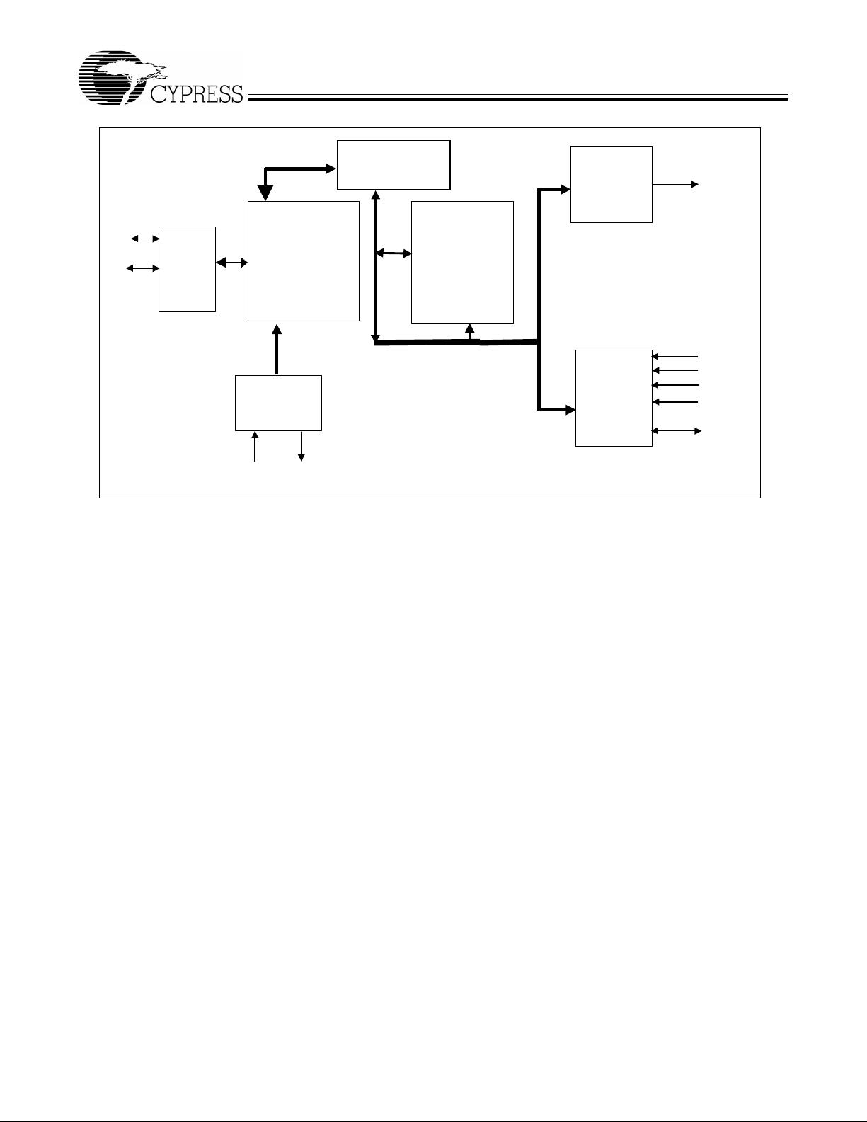
4.1 Block Diagram
The SL811HS is an Embedded USB Host/Slave Controller capable of communicate with either full-speed or low-speed USB
peripherals. The SL811HS can interface to devices such as microprocessors, microcontrollers, DSPs, or directly to a variety of
buses such as ISA, PCMCIA, and others. The SL811HS USB Host Controller conforms to USB Specification 1.1.
The SL811HS USB Host/Slave Controller incorporates USB Serial Interface functionality along with internal full-/low-speed trans-
ceivers. The SL811HS supports and operates in USB full-speed mode at 12 Mbps, or at low-speed 1.5-Mbps mode.
The SL811HS data port and microprocessor interface provide an 8-bit data path I/O or DMA bidirectional, with interrupt support
to allow easy interface to standard microprocessors or microcontrollers such as Motorola or Intel CPUs and many others. Inter-
nally, the SL811HS contains a 256-byte RAM data buffer which is used for control registers and data buffer.
The available package types offered are a 28-pin PLCC (SL811HS) and a 48-pin TQFP package (SL811HST-AC). Both packages
operate at 3.3 VDC. The I/O interface logic is 5V-tolerant.
SL811HS
Document #: 38-08008 Rev. *A Page 5 of 29
4.2 SL811HS Host or Slave Mode Selection [Master/Slave Mode]
SL811HS can work in two modes—host or slave. For slave-mode operation and specification, please refer to the SL811S
specification. This data sheet only covers host-mode operation.
4.3 Features
• The only USB Host/Slave controller for embedded systems in the market with a standard microprocessor bus interface.
• Supports both full-speed (12 Mbps) and low-speed (1.5 Mbps) USB transfer
4.3.1 USB Specification Compliance
• Conforms to USB Specification 1.1
4.3.2 CPU Interface
• Operates as a single USB host or slave under software control
• Low-speed 1.5 Mbps, and full speed 12 Mbps, in both master and slave modes
• Automatic detection of either low- or full-speed devices
• 8-bit bidirectional data, port I/O (DMA supported in slave mode)
• On-chip SIE and USB transceivers
• On-chip single root HUB support
• 256-byte internal SRAM buffer, ping-pong operation
• Operates from 12- or 48-MHz crystal or oscillator (built-in DPLL)
• 5 V-tolerant interface
• Suspend/resume, wake up, and low-power modes are supported
• Auto-generation of SOF and CRC5/16
• Auto-address increment mode, saves memory Read/Write cycles
• Development kit including source code drivers is available
• Backward-compatible with SL11H, both pin and functionality
• 3.3V power source, 0.35 micron CMOS technology
• Available in both a 28-pin PLCC package (SL811HS) and a 48-pin TQFP package (SL811HST-AC).
X1 X2
D+
D-
INTR
nWR
nRD
nCS
nRST
D0-7
GENERATOR
USB
Root-HUB
XCVRS
SERIAL
INTERFACE
ENGINE
RAM
BUFFERS
CONTROL
REGISTERS
INTERRUPT
CLOCK
&
CONTROLLER
PROCESSOR
INTERFACE
Master/Slave
Controller
Figure 4-1. SL811HS USB Host/Slave Controller Functional Block Diagram