
Seediscussions,stats,andauthorprofilesforthispublicationat:https://www.researchgate.net/publication/257728920
PhotovoltaicModuleModelingusing
Simulink/Matlab
Article·December2013
DOI:10.1016/j.proenv.2013.02.069
CITATIONS
14
READS
1,425
4authors:
Someoftheauthorsofthispublicationarealsoworkingontheserelatedprojects:
ContributionstotheControlofAnAsymmetricalSix-phaseInductionMachineViewproject
Fault-tolerantControlofSymmetricalSix-phaseInductionMachineViewproject
KrismadinataChaniago
UniversitasNegeriPadang,Indonesia
17PUBLICATIONS311CITATIONS
SEEPROFILE
NasrudinAbdRahim
UniversityofMalaya
501PUBLICATIONS6,338CITATIONS
SEEPROFILE
WooipingHew
UniversityofMalaya
194PUBLICATIONS1,995CITATIONS
SEEPROFILE
JeyrajSelvaraj
UniversityofMalaya
49PUBLICATIONS911CITATIONS
SEEPROFILE
AllcontentfollowingthispagewasuploadedbyJeyrajSelvarajon27April2017.
Theuserhasrequestedenhancementofthedownloadedfile.Allin-textreferencesunderlinedinblueareaddedtotheoriginaldocument
andarelinkedtopublicationsonResearchGate,lettingyouaccessandreadthemimmediately.

Procedia Environmental Sciences 17 ( 2013 ) 537 – 546
1878-0296
© 2013 The Authors. Published by Elsevier B.V.
Selection and peer-review under responsibility of SUSTAIN conference’s committee and supported by Kyoto University; (OPIR),
(GCOE-ES), (GCOE-HSE), (CSEAS), (RISH), (GCOE-ARS) and (GSS) as co-hosts.
doi: 10.1016/j.proenv.2013.02.069
Available online at www.sciencedirect.com
The 3
rd
International Conference on Sustainable Future for Human Security
SUSTAIN 2012
Photovoltaic module modeling using simulink/matlab
Krismadinata
a
*, Nasrudin Abd. Rahim
a
Hew Wooi Ping
a
, Jeyraj Selvaraj
a
a
University of Malaya Power Energy Dedicated Advanced Centre (UMPEDAC)
Level 4 Wisma R&D University of Malaya Kuala Lumpur 59990 Malaysia
Abstract
This paper describes a method of modeling and simulation photovoltaic (PV) module that implemented in
Simulink/Matlab. It is necessary to define a circuit-based simulation model for a PV cell in order to allow the
interaction with a power converter. Characteristics of PV cells that are affected by irradiation and temperature are
modeled by a circuit model. A simplified PV equivalent circuit with a diode equivalent is employed as model. The
simulation results are compared with difference types of PV module datasheets. Its results indicated that the created
simulation blocks in Simulink/matlab are similar to actual PV modules, compatible to different types of PV module
and user-friendly
© 2012 The Authors. Published by Elsevier B.V.
Selection and/or peer-review under responsibility of SUSTAIN conferences committee and supported by Kyoto
University; (OPIR), (GCOE-ES), (GCOE-HSE), (CSEAS), (RISH), (GCOE-ARS) and (GSS) as co-hosts.
Keywords: modeling; PV module; PV characteristic; simulink/matlab
*E-mail address: [email protected]
Available online at www.sciencedirect.com
© 2013 The Authors. Published by Elsevier B.V.
Selection and peer-review under responsibility of SUSTAIN conference’s committee and supported by Kyoto University;
(OPIR), (GCOE-ES), (GCOE-HSE), (CSEAS), (RISH), (GCOE-ARS) and (GSS) as co-hosts.
538 Krismadinata et al. / Procedia Environmental Sciences 17 ( 2013 ) 537 – 546
1. Introduction
Due to reserve of fossil fuel dwindling and the global warming effect looming large, alternative
energies become popular. The most attention of alternative energies is solar energy. There are two types
of technology that employed solar energy, namely solar thermal and solar cell. A PV cell (solar cell)
converts the sunlight into the electrical energy by the photovoltaic effect. Energy from PV modules offers
several advantages, such as, requirement of little maintenance and no environmental pollution. Recently,
PV arrays are used in many applications, such as, battery chargers, solar powered water pumping systems,
grid connected PV systems, solar hybrid vehicles and satellite power systems.
PV module represents the fundamental power conversion unit of a PV generator system. The output
characteristic of PV module depends on the solar insulation and the cell temperature. Since PV module
has nonlinear characteristics, it is necessary to model it for the design and simulation of maximum power
point tracking (MPPT) for PV system applications [1].
A PV module typically consists of a number of PV cells in series. The conventional technique to
model a PV cell is to study the p-n junction physics [2]. A PV cell has a non-linear voltage-current (V-I)
characteristic which can be modeled using current sources, diode(s) and resistors. Single-diode and
double-diode models are widely used to simulate PV characteristics. The single-diode model emulates the
PV characteristics fairly and accurately. The manufacturer provides information about the electrical
characteristics of PV by specifying certain points in its V-I characteristics which are called remarkable
points [3].
In this paper, a simplified PV equivalent circuit with a diode equivalent as model is proposed. The
main contribution of this work is the implementation of a generalized PV model in the form of masked
block which has a user-friendly icon and dialog in the same way of Matlab/Simulink block libraries.
2. Mathematical model for a photovoltaic cell
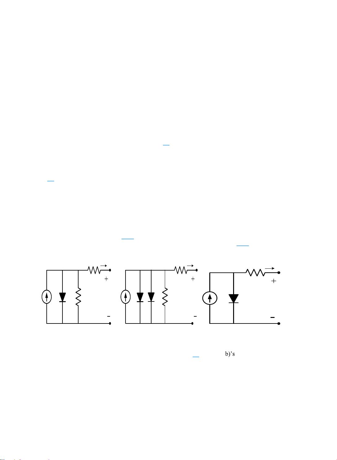
Fig. 1(a)-(b) are models of the most commonly-used PV cell: a current source parallel with one or
two diodes. A single-diode model [4-6] has four components: photo-current source, diode parallel to
source, series of resistor R
s
, and shunt resistor R
sh
. Fig.1(b) is a two-diode model: [7-9] the extra diode is
for better curve-fitting.
L
I
D
I
S
R
Sh
R
I
V
L
I
1D
I
S
R
Sh
R
I
V
2D
I
L
I
D
I
S
R
I
V
(a) (b) (c)
Fig. 1: PV-cell equivalent-circuit models: (a) single-diode model, (b) two-diode model (c) Simplified-PV-equivalent
circuit
The shunt resistance R
sh
is large, so it usually can be neglected [8]. Fig. 1(a- four-parameter models
can, thus, be simplified into Fig. 1c, the simplified equivalent-circuit model of this study.
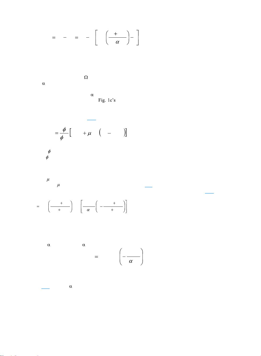
The output voltage V and the load current I relate as:
539
Krismadinata et al. / Procedia Environmental Sciences 17 ( 2013 ) 537 – 546
1exp
0
s
LDL
IRV
IIIII
(1)
where I
L
= light current (A);
I
0
= saturation current (A);
I = load current (A);
V = output voltage (V);
R
S
= series resistance ( );
= thermal voltage timing completion factor (V).
Four parameters (I
L
, I
0
, R
S
, and ) must be determined to obtain the I-V relationship (the reason the model
is called a four-parameter model). equivalent circuit and Equation (1) mask the complexity of
the actual model, for the four parameters are functions of temperature, load current and/or solar
irradiance. Procedures for determining the four parameters are given herewith.
Light Current I
L
; [10-12], states that I
L
can be calculated as:
refCCSCIrefL
ref
L
TTII
,,,
(2)
where
= irradiance (W/m
2
),
ref
= reference irradiance (1000 W/m
2
is used in this study),
I
L,ref
= light current at the reference condition (1000W/m
2
and 25°C),
T
c
= PV cell temperature (°C),
T
c,ref
= reference temperature (25 °C is used in this study),
I,SC
= temperature coefficient of the short-circuit current (A/°C);
Both I
L,ref
and
I,SC
are available on manufacturer datasheet [11].
Saturation Current I
0
; this can be expressed in terms of its value at reference conditions [10-12]:
273
273
1exp
273
273
,
3
,
,00
C
refC
ref
Sgap
C
refC
ref
T
T
q
Ne
T
T
II
(3)
where I
0,ref
= saturation current (A) at reference conditions,
e
gap
= band gap of the material (1.17 eV for Si materials),
N
s
= number of cells in series of a PV module,
q = charge of an electron (1.60217733×10
-19
C),
ref
= the value of at reference conditions.
I
0,ref
can be calculated as:
ref
refoc
refLref
V
II
,
,,0
exp
(4)
where V
oc,ref
= the reference-condition open-circuit voltage (V) of the PV module; its value is
manufacturer-provided.
In [10-12] state that
ref
can be calculated from