


IEEE TRANSACTIONS ON POWER ELECTRONICS, VOL. 22, NO. 2, MARCH 2007 613
Modeling, Analysis and Testing of Autonomous
Operation of an Inverter-Based Microgrid
Nagaraju Pogaku, Student Member, IEEE, Milan Prodanovic
´
, Member, IEEE, and
Timothy C. Green, Senior Member, IEEE
Abstract—The analysis of the small-signal stability of conven-
tional power systems is well established, but for inverter based
microgrids there is a need to establish how circuit and control
features give rise to particular oscillatory modes and which of
these have poor damping. This paper develops the modeling and
analysis of autonomous operation of inverter-based microgrids.
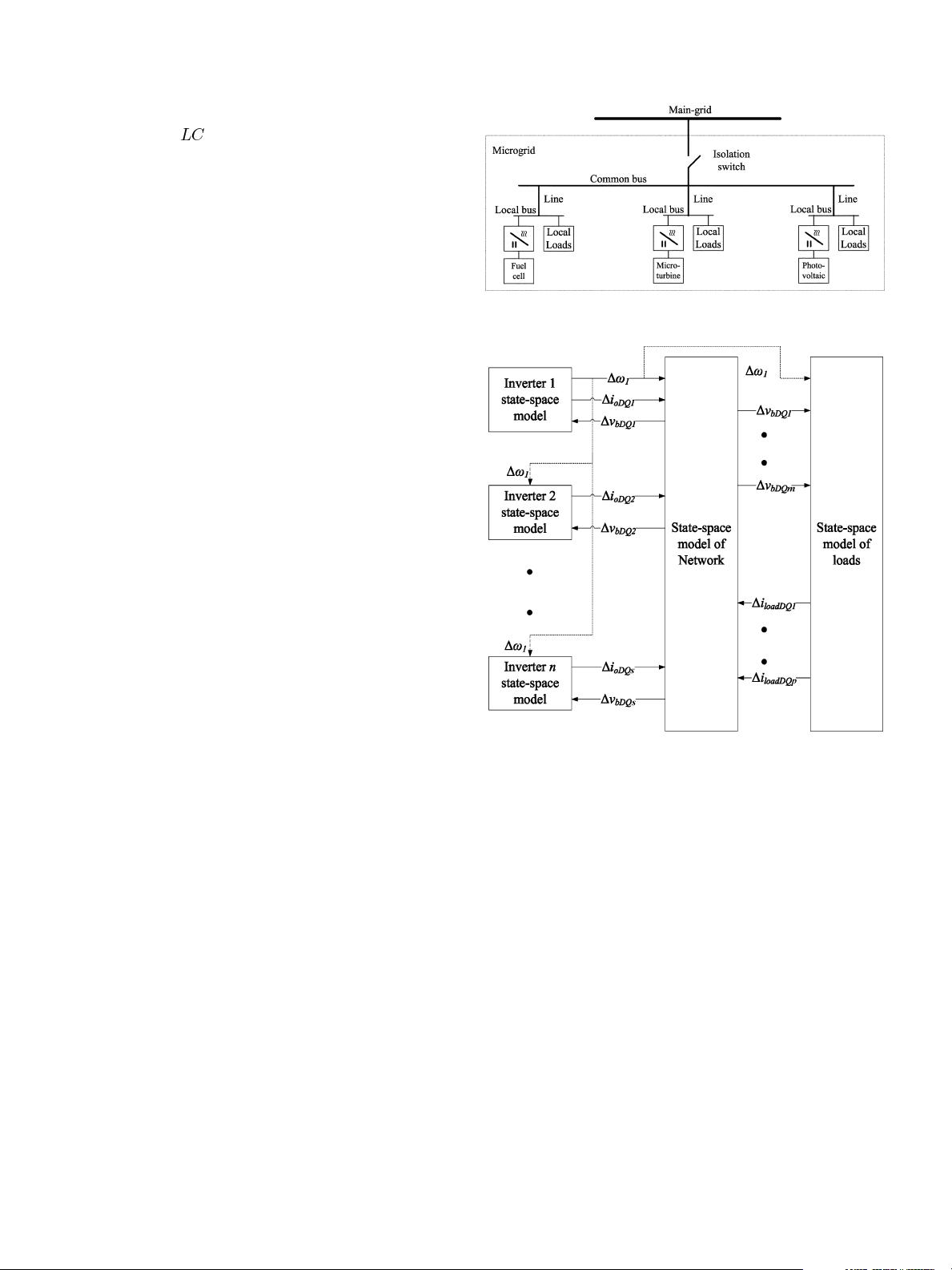
Each sub-module is modeled in state-space form and all are
combined together on a common reference frame. The model
captures the detail of the control loops of the inverter but not the
switching action. Some inverter modes are found at relatively high
frequency and so a full dynamic model of the network (rather
than an algebraic impedance model) is used. The complete model
is linearized around an operating point and the resulting system
matrix is used to derive the eigenvalues. The eigenvalues (termed
“modes”) indicate the frequency and damping of oscillatory
components in the transient response. A sensitivity analysis is also
presented which helps identifying the origin of each of the modes
and identify possible feedback signals for design of controllers
to improve the system stability. With experience it is possible to
simplify the model (reduce the order) if particular modes are
not of interest as is the case with synchronous machine models.
Experimental results from a microgrid of three 10-kW inverters
are used to verify the results obtained from the model.
Index Terms—Inverter, inverter model, microgrid, power con-
trol, small-signal stability.
I. INTRODUCTION
R
ECENT innovations in small-scale distributed power
generation systems combined with technological ad-
vancements in power electronic systems led to concepts of
future network technologies such as microgrids. These small
autonomous regions of power systems can offer increased reli-
ability and efficiency and can help integrate renewable energy
and other forms of distributed generation (DG) [1]. Many forms
of distributed generation such as fuel-cells, photo-voltaic and
micro-turbines are interfaced to the network through power
electronic converters [2]–[5]. These interface devices make the
sources more flexible in their operation and control compared
to the conventional electrical machines. However, due to their
Manuscript received December 8, 2005; revised May 25, 2006. This work
was supported by the Microgrids Workpackage of the Supergen Future Network
Technologies Consortium. Recommended for publication by Associate Editor
F. Z. Peng.
The authors are with the Department of Electrical and Electronic En-
gineering, Imperial College of London, London SW7 2AZ, U.K. (e-mail:
nagaraju.pogaku@imperial.ac.uk; milan.prodanovic@imperial.ac.uk; green@
imperial.ac.uk).
Color versions of one or more of the figures in this paper are available online
at http://ieeexplore.ieee.org.
Digital Object Identifier 10.1109/TPEL.2006.890003
negligible physical inertia they also make the system potentially
susceptible to oscillation resulting from network disturbances.
A microgrid can be operated either in grid connected mode
or in stand-alone mode. In grid connected mode, most of the
system-level dynamics are dictated by the main grid due to the
relatively small size of micro sources. In stand-alone mode, the
system dynamics are dictated by micro sources themselves, their
power regulation control and, to an unusual degree, by the net-
work itself.
One of the important concerns in the reliable operation of a
microgrid is small-signal stability. In conventional power sys-
tems, stability analysis is well established and for the different
frequency ranges (or time horizons) of possible concern there
are models which include the appropriate features. The features
have been established on the basis of decades of experience so
that there are standard models of synchronous machines, gover-
nors and excitation systems of varying orders that are known to
capture the important modes for particular classes of problem.
This does not yet exist for microgrids and may be difficult to
achieve because of the range of power technologies that might
be deployed. However, we can begin by developing full-order
models of inverters and the inverter equivalents of governors and
excitors. Examination of these models applied to various sys-
tems will develop that body of experience that allows reduced
order models to be selected for some problems.
Previous dynamic analysis of standalone systems has been
carried out by assuming an ideal inverter as in [6]. This means
that the closed-loop inner controllers that track voltage and cur-
rent references are assumed to track perfectly, accurately and
quickly. They therefore do not have any effect on the small
signal stability. This assumption is based on the fact that the
closed-loop bandwidth of the inverter is well above the band-
width of power sharing controllers that set the voltage and cur-
rent references. This is a relatively safe assumption for low
power inverters with a high switching frequency but cause im-
portant dynamics to be omitted for large inverters where low
switching frequency limits the control bandwidth of the inner-
most control loop. The modeling approach presented in [7] con-
centrates on stability issues for an individual inverter connected
to a stiff ac bus. This is valuable in illuminating inverter proper-
ties but needs extension to cover the interaction of inverters with
each other and with network dynamics before it can indicate the
nature of stability issues in microgrids.
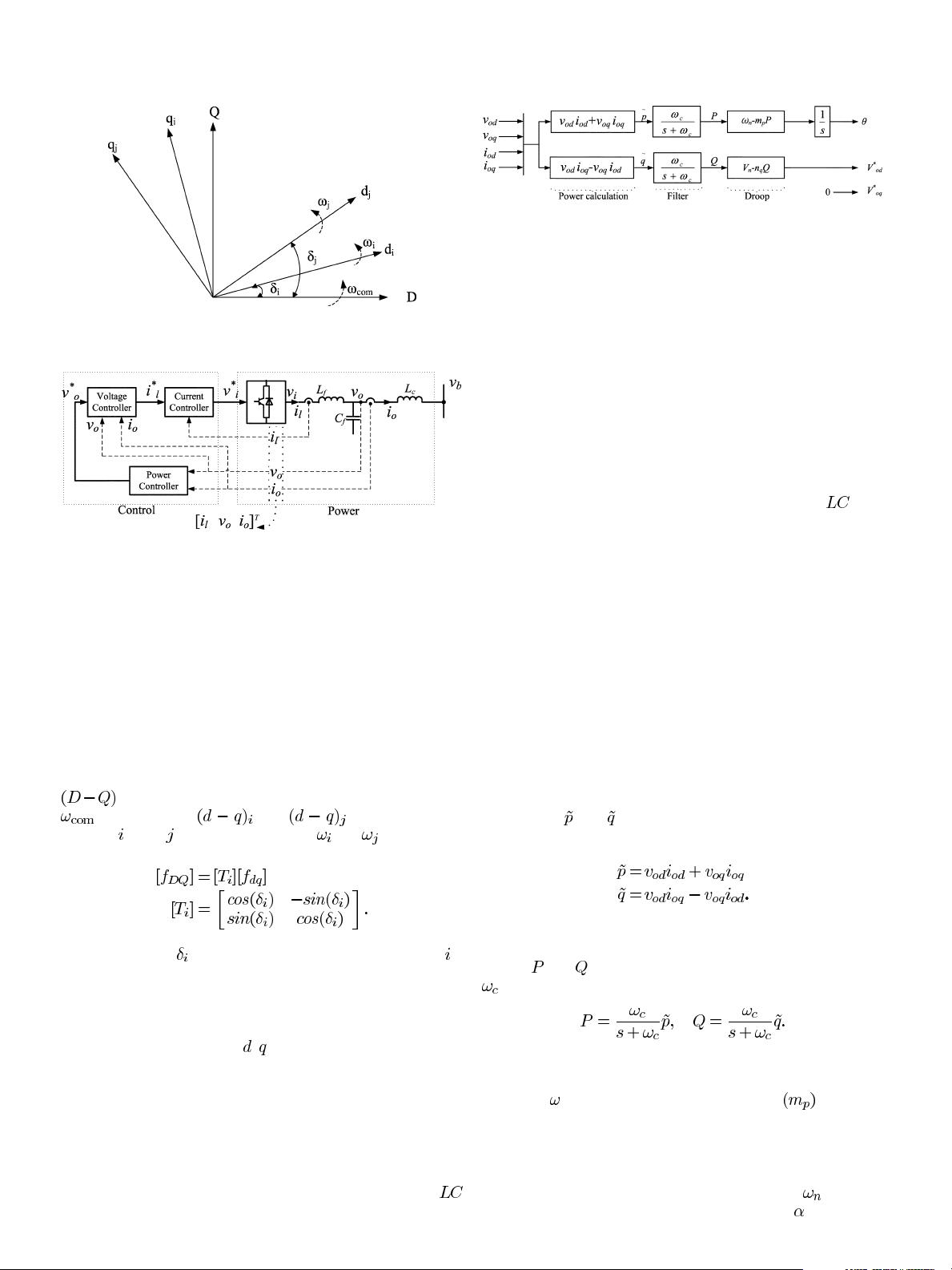
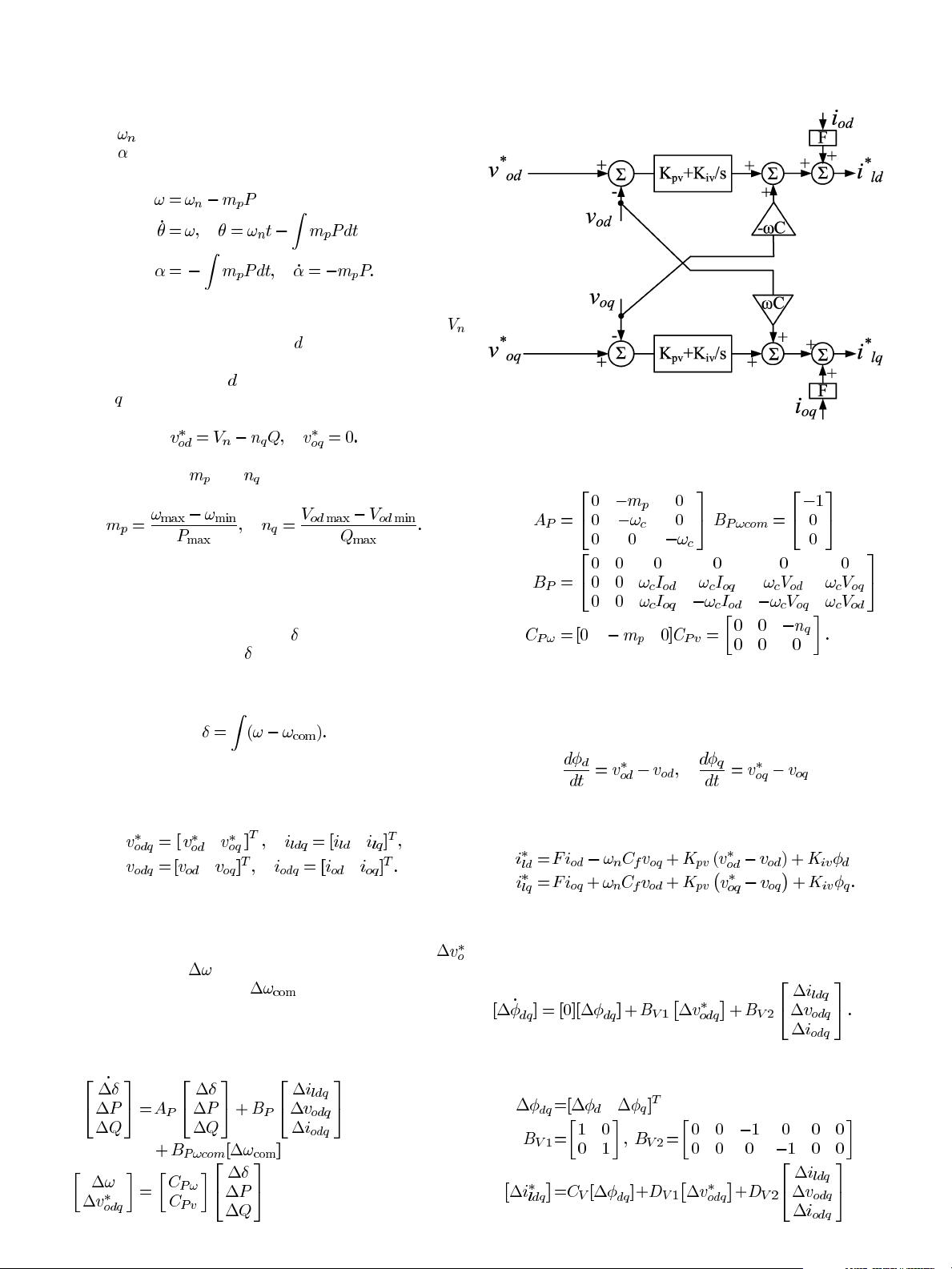
In this paper, a systematic approach to modeling an in-
verter-based microgrid is presented. Each DG inverter will
have an outer power loop based on droop control to share the
fundamental real and reactive powers with other DGs. Inverter
internal controls will include voltage and current controllers
0885-8993/$25.00 © 2007 IEEE


评论0