


Single-Phase PV Inverter
1 Overview
Single-phase PV inverters are commonly used in residential rooftop PV systems. In this application
example, a single-phase, single-stage, grid-connected PV inverter is modeled. The PV system includes
an accurate PV string model that has a peak output power of 3 kW.
2 Model
V
Current
controller
err
out
+
−
Unipolar
Modulator
fs:
25e3
s
v*
vdc
−
+
Sun
Before:
1
After:
0.7
Voltage
controller
Iref
err
Vgrid
V
MPP
controller
ki:
10
ts:
1/100
v0:
388
vref
v,i
A
PV
C:
1.5e-3
v_init:
388
Q1
Q2
Q3
Q4
D1
D2
D3
D4
L:
2e-3
C:
4.7e-6
L:
3e-3
R:
10
R:
0.02
R:
0.03
A
25
Temp[050]ºC
s1
s2
s3
s4
s1
s2
s3
s4
Grid
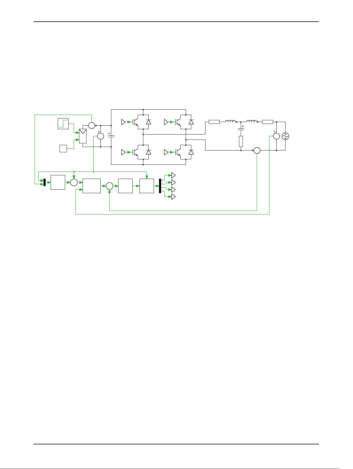
Figure 1: Inverter system
The power generation system is comprised of a solar array that provides a steady-state output of ap-
proximately 380 VDC, an IGBT-based full bridge inverter, and an LCL output filter connected to a
230 V
rms
, 50 Hz single-phase mains.
2.1 PV String Model
The PV string component is based on a non-linear current source that accurately models the IV char-
acteristic with variable inputs of insolation (sun intensity), output voltage, and temperature. Further,
it can be connected in various series and parallel configurations and used as a DC source for both of-
fline and grid-connected systems. The model is based on the Shockley diode equations for accuracy and
can be used to study the interactions between a PV inverter and the supply modules. The typical out-
put current characteristic of the PV model is shown in Fig. 2.
In this example, insolation and temperature-dependent data has been mapped for a BP365 65 W so-
lar module, and the array comprises 22 modules connected in each string, with 2 strings connected in
parallel. The current surface data, is saved in a .mat file and contains information for the characteris-
tic IV curves for an insolation range of 0 to 1 kWhr/m
2
, voltage values between 0 and 25 V, and three
temperatures of 0, 25, and 50
◦
C.
2.2 Control
The control system comprises three control loops: a maximum power point (MPP) controller, a volt-
age controller and a current controller. These can be seen in the circuit diagram in Fig. 1. The outer
control loop is a MPP controller that ensures maximum power is extracted from the PV string for a
given insolation level. To do this, it calculates the optimal PV terminal voltage using a MPP algorithm
known as dP/dV (incremental conductance) control, implemented using a C-Script block. The voltage
control loop, based on a type 2 controller, regulates the PV voltage to this optimal level by controlling
www.plexim.com 1


评论6