Electrical Drives Juha Pyrhönen, LUT, Department of Electrical Engineering
9.1
9. PERMANENT MAGNET SYNCHRONOUS MACHINE (PMSM) ......................................... 1
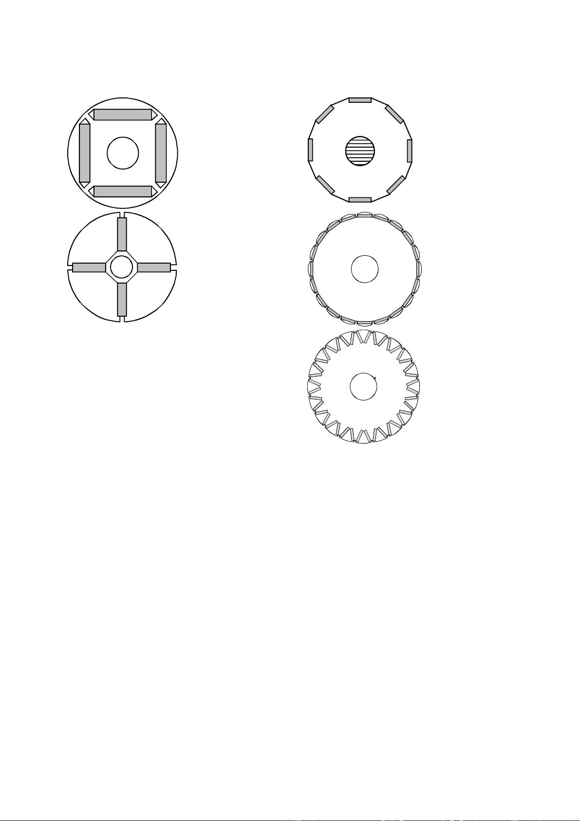
9.1 PMSM Configurations and Machine Parameters ................................................................ 2
9.2 Equivalent Circuit and Vector Diagram of a PMSM ........................................................... 8
9.3 Current Vector Control ...................................................................................................... 11
9.4 i
d
= 0 Control ...................................................................................................................... 11
9.5 Method for Minimizing the Stator Current ........................................................................ 14
9.6 Direct Flux Linkage and Torque Control PMSMDTC ...................................................... 17
9.7 Voltage Reserve and Power Factor .................................................................................... 19
9.8 On Speed and Position Sensorless Control Methods for PM Machines ............................ 25
9.9 Comparison of the Control Methods .................................................................................. 28
9. PERMANENT MAGNET SYNCHRONOUS MACHINE (PMSM)
The development of high-quality permanent magnet materials into commercial production has
encouraged several manufacturers to launch various permanent magnet synchronous machines
(PMSM) into the market. Permanent magnet synchronous machines have been applied to servo
drives for a long time already, and nowadays, there are quite large permanent magnet synchronous
machines also in industrial use. In wind mill generators, the development has currently been in the
direction of permanent magnet machines. In principle, vector control is required for controlling the
PMSM. Previously, the poor qualities of the magnetic materials could considerably restrict the
implementation of a motor control. For instance, due to the poor demagnetization characteristics of
AlNiCo magnets, the so-called i
d
= 0 control was initially adopted in order to ensure the stability of
the polarization. The properties of NdFeB and SmCo magnets instead allow also the use of
demagnetizing current. Demagnetizing current is used in particular when aiming at the field
weakening of a permanent magnet machine; however, a negative current aligned with the d-axis
occurs also in the constant flux range, when aiming at a high power factor for the drive.
The basic differences to the control principles of other AC motors are due to the magnetic
properties of permanent magnets, and particularly to the fact that the permanent magnet material is
a part of the magnetic circuit of the machine, and therefore has a significant influence on its
reluctance. The relative permeability of permanent magnet materials
r
is close to one, and
therefore the effective direct air gap of the PMSM often becomes very large. Thereby also the
inductances of the machine – particularly in machines in which the magnets are located on the rotor
surface – usually remain rather low. Another difference is that the direct synchronous inductance,
when employing embedded magnets, can be less than the quadrature value, while the ratio is the
opposite in a separately excited salient-pole synchronous machine.
The field weakening of a PM machine has to be implemented by using a demagnetizing stator
current. If the inductances are very low, the field weakening is not a rational option. In the surface
magnet type servo motors, the per unit value of the synchronous inductance is typically in the range
l
d
= 0.2−0.4. An adequate rotation speed range is often achieved by dimensioning the rated
frequency of the machine to be sufficiently high. When employing embedded magnets, however,
the inductances may be dimensioned so high that the rotation speed range can be expanded. Often
when staying within the limits of the rated current, the upper limit remains at about double the rated
speed at maximum. However, when applying field weakening, it should be borne in mind that the
back emf caused by the permanent magnets is directly proportional to the rotation speed of the
machine. If the demagnetizing current is lost for some reason, the inverter has to withstand this
voltage undamaged; however, the danger of the breakdown of the inverter is obvious. The