
© Siemens AG 2015. All rights reserved
A5E36156122, 09.2015
1
SITOP PSU8600
6EP3436-8SB00-2AY0 (20 A)
6EP3437-8SB00-2AY0 (40 A)
Betriebsanleitung (kompakt)
Operating Instructions (
compact)
Instrucciones de servicio (resumidas)
操作说明
(精简版)
Notice de service (compacte)
Istruzioni op
erative (descrizione sintetica)
Руководство по эксплуатации
(компактное)
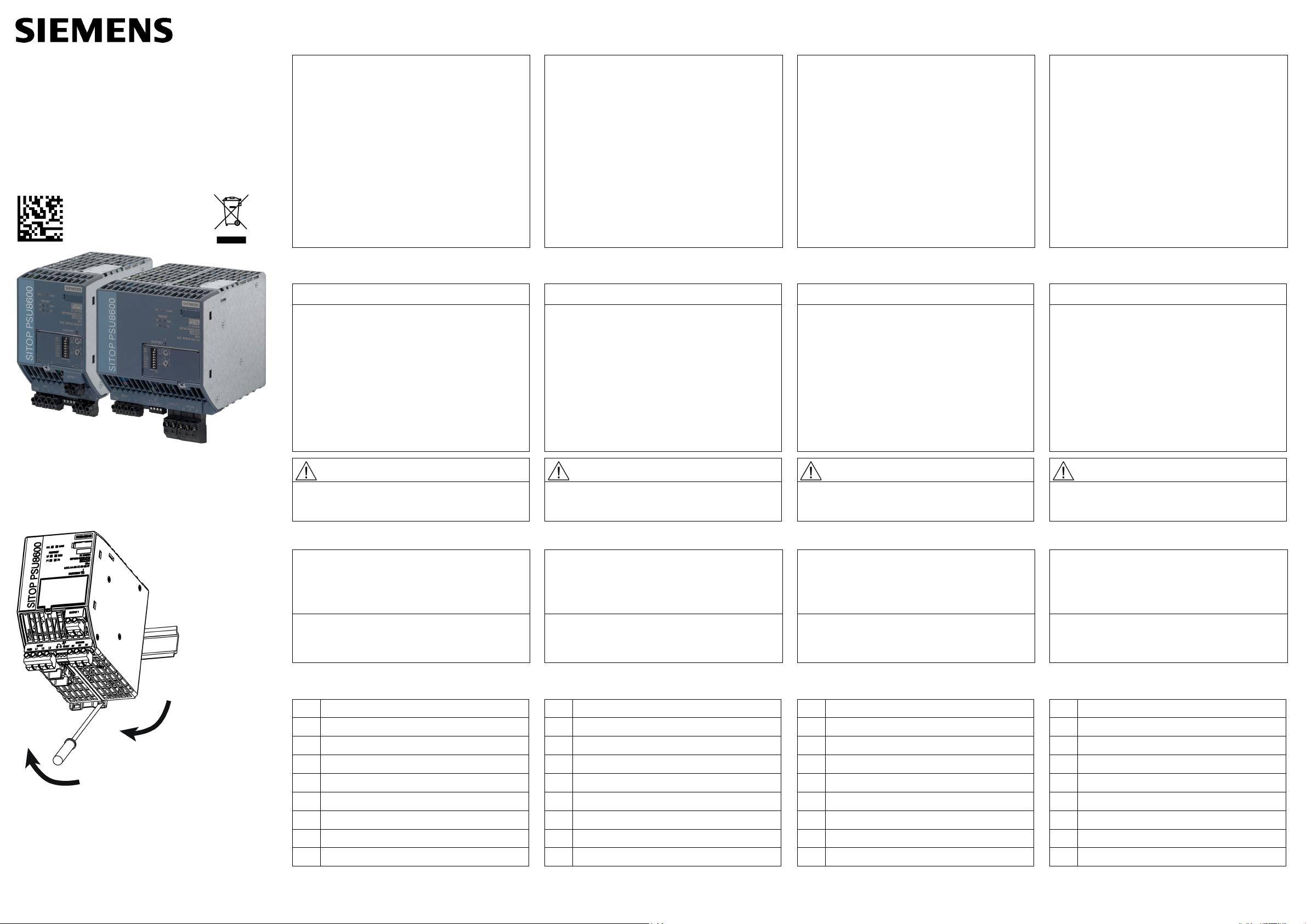
Bild
1: Ansicht Geräte
Figure
1: View of devices
Figura
1: Vista de aparatos
图
1: 设备外观
Figure
1: Vue des appareils
Figura
1: Vista degli apparecchi
Рис.
1: Внешний вид устройств
Bild
2: Montage/Demontage
Figure
2: Mounting/removal
Figura
2: Montaje/desmontaje
图
2: 安装/拆卸
Figure
2: Montage/démontage
Figura
2: Montaggio/smontaggio
Рис. 2: Монтаж/демонтаж
DEUTSCH
Beschreibung
Das SITOP-Stromversorgungssystem PSU8600 besteht
aus Einbaugeräten (und ist somit in einen Verteilerkasten
oder Schaltschrank einzubauen), Schutzart IP20,
Schutzklasse I.
Das Grundgerät SITOP PSU8600 ist eine geregelte
Stromversorgung zum Anschluss an ein 3-phasiges
Wechselstromnetz (TN-, TT-Netz nach VDE 0100 T 300 /
IEC 364-3) mit Nennspannungen 3 AC 400 - 500 V, 50 -
60 Hz oder ein IT-Netz mit Nennspannung 3 AC 400 -
500 V, 50 - 60 Hz. Das Gerät besitzt einen geregelten
potentialfreien Ausgang mit einem Einstellbereich 5 bis 28 V
DC. Der Ausgangsstrom beträgt maximal 20 A (6EP3436-
8SB00-2AY0) bzw. maximal 40 A (6EP3437-8SB00-2AY0),
mit einstellbarer elektronischer Überlastabschaltung.
Das System agiert als PROFINET I/O-Device und verfügt
über einen 2-Port Switch.
Siehe
Bild 1 Ansicht Geräte (Seite 1)
Sicherheitshinweise
ACHTUNG
Der einwandfreie und sichere Betrieb dieses
Gerätes/Systems setzt sachgemäßen Transport,
sachgemäße Lagerung, Aufstellung und Montage
sowie sorgfältige Bedienung und Instandhaltung
voraus.
Dieses Gerät/System darf nur unter Beachtung der
Instruktionen und Warnhinweise der zugehörigen
technischen Dokumentation eingerichtet und
betrieben werden.
Nur qualifiziertes Personal darf das Gerät/System
installieren und in Betrieb setzen.
WARNUNG
POTENZIOMETEREINSTELLUNG ODER
SCHALTERBETÄTIGUNG NUR IN NICHT-
EXPLOSIVER UMGEBUNG DURCHFÜHREN!
Montage
Montage auf Normprofilschiene TH35-15 (EN 60715).
Das Gerät ist so zu montieren, dass die Eingangs- und
Ausgangsklemmen unten sind. Unterhalb und oberhalb
des Gerätes muss mindestens ein Freiraum von je
50 mm eingehalten werden.
Bei Installation des Gerätes in explosionsgefährdeter
Umgebung (II 3G Ex nA nC IIC T4 Gc) ist dieses in
einen Verteilerkasten mit Schutzart IP54 oder höher
einzubauen.
Sie
he Bild 2 Montage/Demontage (Seite 1)
Aufbau
①
AC-Eingang
②
DC-Ausgang
③
0 Volt-Klemme
④
Meldekontakt, Reset
⑤
Ethernet/PROFINET-Schnittstelle
⑥
LED-Anzeigen (OK, MAN, SF, RUN, P1, P2)
⑦
Hutschienenschieber
⑧
Konvektion
⑨
Freiraum oberhalb/unterhalb
ENGLISH
Description
The SITOP power supply system PSU8600 comprises
built-in devices (and can therefore be installed in
distribution boxes or control cabinets), degree of
protection IP20, protection class I.
The basic SITOP PSU8600 device is a regulated power
supply that is connected to a 3-phase AC line supply
(TN, TT system according to VDE 0100 T 300 / IEC
364-3) with a rated voltage of 3 AC 400 - 500 V, 50 -
60 Hz or an IT system with a rated voltage of 3 AC 400
- 500 V, 50 - 60 Hz. The device has a regulated,
isolated output with a setting range of 5 to 28 V DC.
The output current is maximum 20 A (6EP3436-8SB00-
2AY0) or maximum 40 A (6EP3437-8SB00-2AY0), with
adjustable electronic overload shutdown.
The system acts as PROFINET I/O device and is
equipped with a 2-port switch.
See
Figure 1 View of devices (Page 1)
Safety information
NOTICE
Appropriate transport, proper storage, mounting, and
installation, as well as careful operation and service,
are essential for the error-free, safe and reliable
operation of the device/system.
Setup and operation of this device/system are
permitted only if the instructions and warnings of the
corresponding documentation are observed.
Only qualified personnel are allowed to install the
device/system and set it into operation.
WARNING
OPERATE POTENTIOMETERS OR SWITCHES IN
NON-HAZARDOUS AREAS ONLY!
Mounting
Mounted on a standard mounting rail TH35-15 (EN 60715).
The device must be mounted in such a way that the input
and output terminals are at the bottom. A clearance of at
least 50 mm must be maintained above and below the
device.
If the device is to be used in a hazardous zone ( II 3G
Ex nA nC IIC T4 Gc) it must be installed in a distribution
box with degree of protection IP54 or higher.
See
Figure 2 Mounting/removal (Page 1)
Structure
①
AC input
②
DC output
③
0 Volt terminal
④
Signaling contact, reset
⑤
Ethernet/PROFINET interface
⑥
LED displays (OK, MAN, SF, RUN, P1, P2)
⑦
DIN rail slider
⑧
Convection
⑨
Clearance above/below
ESPAÑOL
Descripción
El sistema de alimentación SITOP PSU8600 está formado
por aparatos para montaje en rack (y, por tanto, debe
montarse en cajas de distribución o armarios de distribu-
ción) con grado de protección IP20, clase de protección I.
El aparato básico SITOP PSU8600 es una fuente de ali-
mentación regulada para la conexión a una red alterna
trifásica (red TN o TT según VDE 0100 T 300 / IEC 364-3)
con tensiones nominales de 3 AC 400-500 V, 50/60 Hz, o a
una red IT con tensión nominal 3 AC 400-500 V, 50/60 Hz.
El aparato posee una salida regulada aislada y con un
rango de ajuste entre 5 y 28 V DC. La intensidad de salida
máxima es de 20 A (6EP3436-8SB00-2AY0) o bien 40 A
(6EP3437-8SB00-2AY0), con desconexión por sobrecarga
electrónica ajustable.
El sistema actúa como dispositivo I/O PROFINET y dispone
de un switch de 2 puertos.
Ver
Figura 1 Vista de aparatos (Página 1)
Consignas de seguridad
ATENCIÓN
El funcionamiento correcto y seguro de este
aparato/sistema presupone un transporte, un
almacenamiento, una instalación y un montaje
conformes a las prácticas de la buena ingeniería,
así como un manejo y un mantenimiento rigurosos.
Este aparato/sistema debe ajustarse y utilizarse
únicamente teniendo en cuenta las instrucciones y
advertencias de la documentación técnica
correspondiente.
La instalación y puesta en marcha del
aparato/sistema debe encomendarse
exclusivamente a personal cualificado.
ADVERTENCIA
¡AJUSTAR EL POTENCIÓMETRO O ACCIONAR
INTERRUPTORES SOLO EN ENTORNOS NO
EXPLOSIVOS!
Montaje
Montaje en perfil normalizado TH35-15 (EN 60715).
El aparato debe montarse de modo que los bornes de
entrada y salida queden abajo. Por encima y por
debajo del aparato debe dejarse un espacio libre de al
menos 50 mm.
Si se va a instalar el aparato en una atmósfera
potencialmente explosiva (II 3G Ex nA nC IIC T4 Gc),
deberá montarse en una caja con grado de protección
IP54 o superior.
Ver
Figura 2 Montaje/desmontaje (Página 1)
Diseño
①
Entrada AC
②
Salida DC
③
Borne de 0 voltios
④
Contacto de señalización, reset
⑤
Interfaz Ethernet/PROFINET
⑥
Indicadores LED (OK, MAN, SF, RUN, P1, P2)
⑦
Corredera de fijación a perfil
⑧
Convección
⑨
Espacio libre arriba/abajo
简体中文
说明
PSU8600 SITOP电源系统由内置设备构成(因此本系统
应安装在配电箱或开关柜内),防护方式IP20,防护等
级 I。
基本设备SITOP PSU8600是一款用于连接额定电压 3
AC 400 - 500 V,50 - 60 Hz 的三相交流电网(TN、TT
电网,符合VDE 0100 T 300 / IEC 364-3)或连接到额
定电压 3 AC 400 - 500 V,50 - 60 Hz 的 IT 电网的稳定
电源。设备具备设定范围在 5 至 28 V DC 的无源稳定输
出。最大输出电流为 20 A (6EP3436-8SB00-2AY0) 或
者 40 A (6EP3437-8SB00-2AY0),具有可调式电控过载
脱扣保护功能。
该系统用作PROFINET I/O 设备,其具备一个 2 端口交
换机。
参见图 1 设备外观 (页 1)
安全提示
注意
本设备/系统的安全正常运行依赖于正确规范的运输、
存放、装配、安装作业以及仔细谨慎的操作和维护。
请务必阅读并遵守本设备/系统技术文档中包含的规定
和警示,否则禁止安装和运行本设备。
本设备/系统仅允许由专业技术人员安装和调试。
警告
仅允许在无爆炸危险的环境下执行电位计设置和开关
操作!
安装
TH35-15 凹顶导轨 (EN 60715) 上的安装。
安装设备时应使输入端子和输出端子位于下方。设备的
上方和下方必须至少保留 50 mm 的通风空间。
在爆炸危险环境(II 3G Ex nA nC IIC T4 Gc)下安装设
备时 ,必须将设备安装在防护方式 IP54 或防护等级更
高的配电箱内。
参见图 2 安装/拆卸 (页 1)
结构
①
交流输入
②
直流输出
③
0 V 端子
④
信号触点,复位
⑤
以太网/PROFINET 接口
⑥
LED 显示(OK、MAN、SF、RUN、P1、P2)
⑦
导轨滑块
⑧
对流
⑨
上方/下方空间

剩余7页未读,继续阅读
资源评论


weixin_38744207
- 粉丝: 344
- 资源: 2万+


最新资源
- Java源码ssm框架的固定设备资产管理系统-毕业设计论文-期末大作业.rar
- Java源码ssm框架的个性化影片推荐系统-毕业设计论文-期末大作业.rar
- Java源码ssm框架的家用电器销售系统-毕业设计论文-期末大作业.rar
- Java源码ssm框架的教学质量评价评教系统-毕业设计论文-期末大作业.rar
- Java源码ssm框架的交通事故档案管理系统-毕业设计论文-期末大作业.rar
- Java源码ssm框架的列车火车高铁票务信息管理系统-毕业设计论文-期末大作业.rar
- Java源码ssm框架的咖啡馆管理系统-毕业设计论文-期末大作业.rar
- Java源码ssm框架的课程思政元素收集系统-毕业设计论文-期末大作业.rar
- Java源码ssm框架的美好生活九宫格日志网-毕业设计论文-期末大作业.rar
- Java源码ssm框架的母婴儿用品网站-毕业设计论文-期末大作业.rar
- Java源码ssm框架的美食推荐管理系统-毕业设计论文-期末大作业.rar
- Java源码ssm框架的农产品供销服务系统-毕业设计论文-期末大作业.rar
- Java源码ssm框架的社区疫情防控管理系统-毕业设计论文-期末大作业.rar
- Java源码ssm框架的人才小区公寓社区物业管理系统-毕业设计论文-期末大作业.rar
- Java源码ssm框架的师生交流答疑作业系统-毕业设计论文-期末大作业.rar
- Java源码ssm框架的文物管理系统-毕业设计论文-期末大作业.rar
资源上传下载、课程学习等过程中有任何疑问或建议,欢迎提出宝贵意见哦~我们会及时处理!
点击此处反馈


