2
Abstract
This paper discusses the design of a 5–6 GHz
Single Balanced Mixer using Agilent’s
HSMS-286B. The mixer development begins
with simulations on diode’s impedance using
Agilent’s Advanced Design System (ADS). Based
on simulated data, a single diode mixer is then
designed and verified through ADS. Assump-
tions were made in IF matching requirement
when combining the two single diode mixers
into a balanced form and the entire balanced
structure is again verified using ADS. The
actual mixer was physically built and fairly
good performance was obtained.
Introduction
Many emerging wireless applications concentrate
on the 5 to 6 GHz band such as 5.8 GHz ISM and
HiperLAN II. This is to be expected as the
current 2.4 GHz band for ISM and wireless LAN
is being fully occupied. A complete integrated
circuit solution for these applications operating
at 5 to 6 GHz may not be cheaply available and
many designs still require discrete solutions on
the Rx front end particularly the Low Noise
Amplifier and the receiver’s first mixer. This
paper discusses a design of such a mixer. This
includes the conceptual design, simulation and
actual measured performance when the mixer
was physically built.
The quadrature hybrid required for the balanced
structure was implemented using a quadrature
coupler, 1M803 from Anaren. This approach
leads to a more performance-optimized and
compact design with shorter development time
compared to implementing the quadrature
hybrid using etched branchline coupler. A
picture of such a mixer is shown in Fig. 1.
Figure 1. Photograph of the 5-6 GHz single balanced mixer.
The Schottky Diode
Mixer conversion loss can be minimized by
carefully choosing the schottky diode for mixer
application. Low junction capacitance, C
jo
and
low series resistance, R
s
are the two important
characteristics of a schottky diode for mixer
application. The Agilent’s HSMS-286B is single
diode in a three lead SC-70 package which
provides low junction capacitance and series
resistance and is an excellent candidate for this
mixer design.
Data from factory indicates the HSMS-286B has
an average C
jo
of about 0.14 pF and an average R
s
of about 5.1Ω. It was shown that the theoretical
conversion loss of such a mixer can be predicted
using the equation below if the LO drive level is
sufficiently high making the conduction angle of
the diode close to 180° :
'
9179.3
o
B
c
Z
R
f
f
dB)Conv.Loss( ++=
where,
js
c
CR
f
π
2
1
=
is the cut-off frequency of the Schottky diode.
Therefore, from the above equation, low series
resistance and junction capacitance of a schottky
diode are two obvious requirements to keep the
cut-off frequency of the diode well above the
frequency of which the diode will be operating as
a mixer. This would keep the conversion loss low
and as close as possible to the theoretical ideal
conversion loss of 3.9 dB (with no harmonic
suppression and image enhancement). Figure 2
shows a circuit model of a HSMS-286B which is
used in simulation.
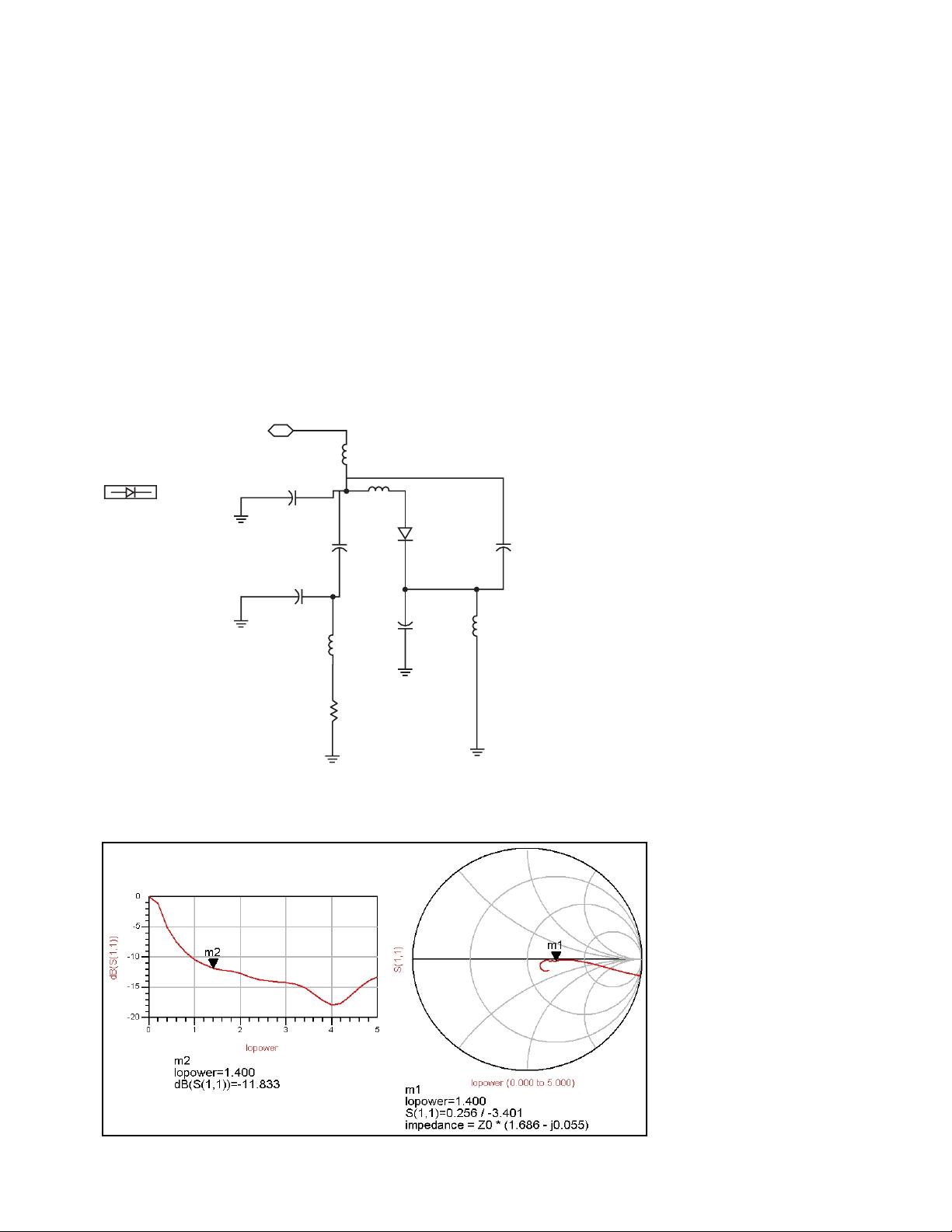
Design Methodology
In the process of designing the mixer, ADS
simulations were heavily relied upon to provide
insight to the various impedance levels of the
diode and their variations across frequency and
LO power levels. At the initial stage, simulations
were done on single schottky diode to obtain the
diode impedance at IF, LO and RF frequencies. A
LO drive level were then chosen and the required
IF, RF and LO matching and filtering network
were then determined and simulated. The single-
ended-single-diode mixer was then simulated by
combining the single diode with the embedding
network. This was followed by simulation of a