没有合适的资源?快使用搜索试试~ 我知道了~
资源推荐
资源详情
资源评论
![pdf](https://img-home.csdnimg.cn/images/20210720083512.png)
![rar](https://img-home.csdnimg.cn/images/20210720083606.png)
![zip](https://img-home.csdnimg.cn/images/20210720083736.png)
![pdf](https://img-home.csdnimg.cn/images/20210720083512.png)
![rar](https://img-home.csdnimg.cn/images/20210720083606.png)
![m](https://img-home.csdnimg.cn/images/20210720083646.png)
![zip](https://img-home.csdnimg.cn/images/20210720083736.png)
![application/pdf](https://img-home.csdnimg.cn/images/20210720083512.png)
![rar](https://img-home.csdnimg.cn/images/20210720083606.png)
![zip](https://img-home.csdnimg.cn/images/20210720083736.png)
![thumb](https://img-home.csdnimg.cn/images/20210720083646.png)
![pdf](https://img-home.csdnimg.cn/images/20210720083512.png)
![zip](https://img-home.csdnimg.cn/images/20210720083736.png)
![rar](https://img-home.csdnimg.cn/images/20210720083606.png)
![](https://csdnimg.cn/release/download_crawler_static/7925745/bg1.jpg)
Evaluation Board User Guide
UG-207
One Technology Way • P. O. Box 9106 • Norwood, MA 02062-9106, U.S.A. • Te l: 781.329.4700 • Fax: 781.461.3113 • www.analog.com
Evaluation Board for 1 GSPS DDS with 14-Bit DAC
PLEASE SEE THE LAST PAGE FOR AN IMPORTANT
WARNING AND LEGAL TERMS AND CONDITIONS.
Rev. A | Page 1 of 16
FEATURES
Full-featured evaluation board for the AD9910
PC evaluation software for control and measurement of the
AD9910
USB interface
Graphic user interface (GUI) software with frequency sweep
capability for board control and data analysis
Factory tested and ready to use
PACKAGE CONTENTS
AD9910 evaluation board
AD9910/PCBZ installation software CD
USB cable
GENERAL DESCRIPTION
This user guide describes how to set up and use the AD9910
evaluation board. The AD9910 is a 1 GSPS DDS with a
14-bit DAC.
The evaluation board software provides a graphical user interface
(GUI) for easy communication with the device along with many
user-friendly features such as the mouse-over effect.
This user guide is intended for use in conjunction with the
AD9910 data sheet, which is available from Analog Devices,
Inc., at www.analog.com.
EVALUATION BOARD BLOCK DIAGRAM
USB
INTERFACE
DC POWER
HEADER
REFERENCE
CLOCK
PARALLEL
DATA
PORT
SPI
DAC OUT
AD9910
TO PC
07481-001
MULTICHIP
SYNC
Figure 1.
![](https://csdnimg.cn/release/download_crawler_static/7925745/bg2.jpg)
UG-207 Evaluation Board User Guide
Rev. A | Page 2 of 16
TABLE OF CONTENTS
Features .............................................................................................. 1
Package Contents.............................................................................. 1
General Description......................................................................... 1
Evaluation Board Block Diagram................................................... 1
Revision History ............................................................................... 2
Evaluation Board Hardware............................................................ 3
Requirements ................................................................................ 3
Setting Up the Evaluation Board................................................ 3
Connectors .................................................................................... 3
Jumpers .......................................................................................... 3
Evaluation Board Layout............................................................. 4
Evaluation Board Software.............................................................. 5
Installing the Software..................................................................5
Installing the Driver......................................................................5
Launching the Program................................................................5
Control Window............................................................................7
Profiles Window............................................................................9
Single-Tone Mode .........................................................................9
View Windows............................................................................ 11
OSK and Digital Ramp Control ............................................... 12
Multichip Sync Control ............................................................. 13
RAM Operation.......................................................................... 14
Debug........................................................................................... 15
Register Map (Software Buffer) Values ................................... 15
REVISION HISTORY
10/10—Rev. 0 to Rev. A
Document Title Changed from AD9910/PCBZ to
UG-207.................................................................................Universal
Updated Format..................................................................Universal
Changes to Device Clock Oscillator Options Section ................. 3
Changes to Power Down Digital, DAC, Clock Input, and Aux
DAC Section...................................................................................... 8
Change to DUT I/O Section ......................................................... 16
Deleted Ordering Information Section ....................................... 17
4/08—Revision 0: Initial Version
![](https://csdnimg.cn/release/download_crawler_static/7925745/bg3.jpg)
Evaluation Board User Guide UG-207
Rev. A | Page 3 of 16
EVALUATION BOARD HARDWARE
REQUIREMENTS
To successfully use the evaluation board and run the software,
the requirements listed in Table 1 must be met.
Table 1. AD9910/PCBZ Requirements
Item Requirement
Operating
System
Windows® 98/ME/2000/XP
Processor Pentium® I or later
Memory 128 MB minimum
Ports One USB port
Clocking
Signal generator capable of generating
sinusoidal waves of at least 0 dBm, up to at
least 10 MHz
Power Supplies
Capability to generate at least two
independent dc voltages (1.8 V/3.3 V)
Measurement
Appropriate measurement device, such as a
spectrum analyzer or a high bandwidth
oscilloscope
Cables
USB 1.1/2.0 cable, and SMA-to-X cables (X =
SMA or BNC, depending on the connector of
the device interfacing with the board)
SETTING UP THE EVALUATION BOARD
DC Power Supply
The AD9910 evaluation board has two power supply connectors
(four pins each): TB1 and TB2. TB1 powers the USB interface
circuitry, the digital I/O interface, and the digital core. TB2
powers the DAC and the clock input circuitry.
CONNECTORS
Table 2 shows the necessary connections and the appropriate
biasing voltage.
Table 2. Connections and Biasing Voltage
Connector Pin No. Label Voltage (V)
TB1 1 VCC_USB 3.3
TB1 2 GND 0
TB1 3 DVDD_IO 3.3
TB1 4 DVDD 1.8
TB2 1, 3 GND 0
TB2 2 DAC_VDD 3.3
TB2 4 CLK_VDD 1.8
Device Clock Oscillator Options
The AD9910 architecture provides the user with three options
when providing an input signal to the part. The first option allows
the user to provide a high frequency input signal, connected to J1.
The second option allows the user to connect using a lower input
reference frequency, enabling the clock multiplier, and connects
through J1. The third option allows the user to connect a crystal
resonator on the backside of the board.
Note that the AD9910 evaluation board does not populate the
PLL loop filter components. Therefore, to use the internal PLL of
the AD9910, the user must solder down these components, or
else the PLL is not stable. The AD9910 data sheet has helpful
formulas to calculate the appropriate values. In addition, an Excel
file to help choose the loop filter component values is available at
www.analog.com. Go to the AD9910 product page and click on
the Evaluation Boards and Development Kits tab.
To enable the crystal mode, switch the jumper, W7, to the XTAL
mode. Remove C51 and 52. Place 0 (zero) Ω resistors at R4 and
R11 on the backside of the board. The crystal oscillates at 25 MHz.
Refer to the AD9910 data sheet for details on the maximum input
speeds and input sensitivities of these two inputs.
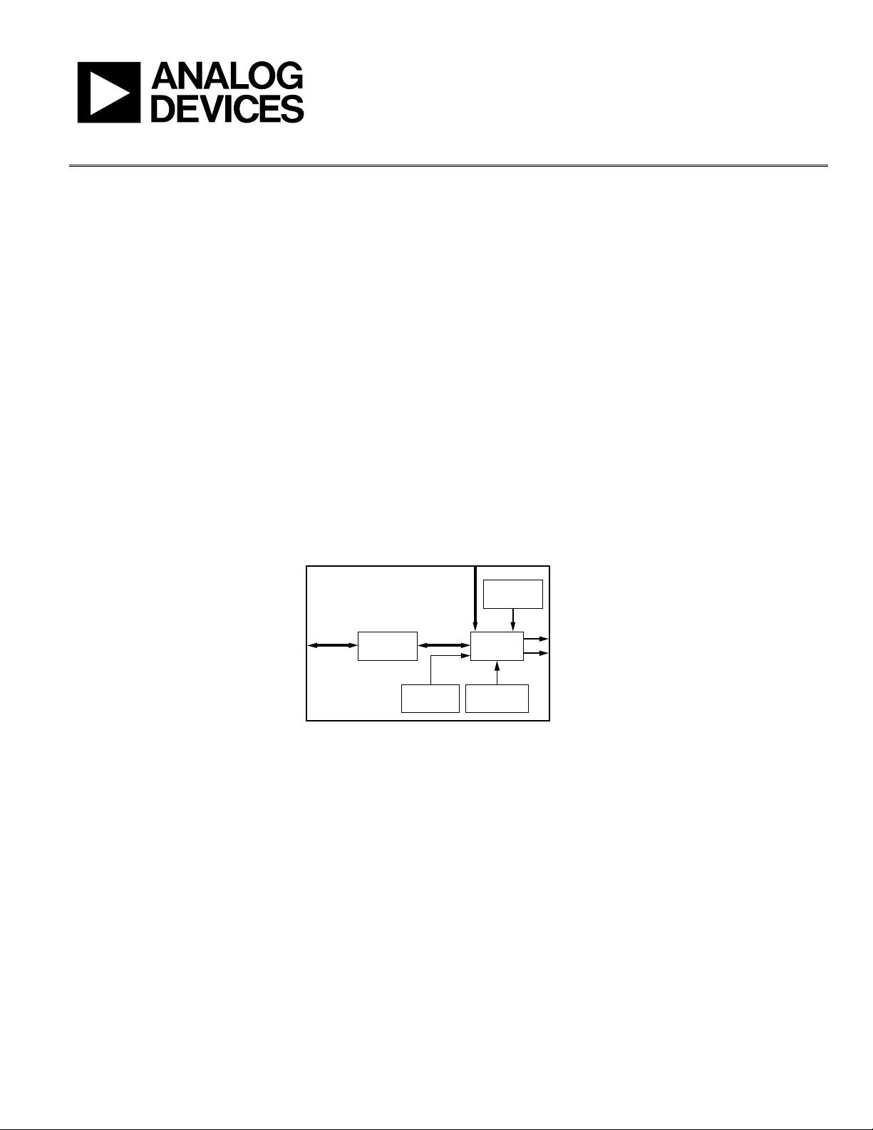
Device Communication Requirements
Two interface options are available on the evaluation board.
• USB 1.1/2.0
• Header row (U5 and U9), which places the part under the
control of an external controller (such as a microprocessor,
FPGA, or DSP)
Analog Devices provides a GUI for the PC; it does not provide
control software for external controllers.
JUMPERS
Use the jumper settings listed in Table 3 to enable different
modes of communication.
Table 3. Jumper Settings for Communication Modes
Mode Settings
PC Control,
USB Port
Set Jumper W1 and Jumper W2 to enable. Set
Jumper W4 to enable. Place a jumper on W5, W6,
and W3.
External
Control
Set Jumper W1and Jumper W2 to disable. Set
Jumper W4 to disable. Remove the jumper on
W5, W6, and W3.
Jumper W1, Jumper W2, and Jumper W4 enable the USB
circuitry to control the AD9910. Jumper W3 controls the
EEPROM, used in starting up the USB circuitry. Jumper W5
and Jumper W6 control Signal SDO and Signal SDIO to and
from the AD9910.
剩余15页未读,继续阅读
资源评论
![avatar-default](https://csdnimg.cn/release/downloadcmsfe/public/img/lazyLogo2.1882d7f4.png)
![avatar](https://profile-avatar.csdnimg.cn/dbf2dcc7f5c346a195c463cf4583a077_wdlhgd.jpg!1)
wdlhgd
- 粉丝: 7
- 资源: 11
上传资源 快速赚钱
我的内容管理 展开
我的资源 快来上传第一个资源
我的收益
登录查看自己的收益我的积分 登录查看自己的积分
我的C币 登录后查看C币余额
我的收藏
我的下载
下载帮助
![voice](https://csdnimg.cn/release/downloadcmsfe/public/img/voice.245cc511.png)
![center-task](https://csdnimg.cn/release/downloadcmsfe/public/img/center-task.c2eda91a.png)
最新资源
- 打包和分发Rust工具.pdf
- SQL中的CREATE LOGFILE GROUP 语句.pdf
- C语言-leetcode题解之第172题阶乘后的零.zip
- C语言-leetcode题解之第171题Excel列表序号.zip
- C语言-leetcode题解之第169题多数元素.zip
- ocr-图像识别资源ocr-图像识别资源
- 图像识别:基于Resnet50 + VGG16模型融合的人体细胞癌症分类模型实现-图像识别资源
- C语言-leetcode题解之第168题Excel列表名称.zip
- C语言-leetcode题解之第167题两数之和II-输入有序数组.zip
- C语言-leetcode题解之第166题分数到小数.zip
资源上传下载、课程学习等过程中有任何疑问或建议,欢迎提出宝贵意见哦~我们会及时处理!
点击此处反馈
![feedback](https://img-home.csdnimg.cn/images/20220527035711.png)
![feedback-tip](https://img-home.csdnimg.cn/images/20220527035111.png)
安全验证
文档复制为VIP权益,开通VIP直接复制
![dialog-icon](https://csdnimg.cn/release/downloadcmsfe/public/img/green-success.6a4acb44.png)