


Secure digital memory card interface SMSxxxAF, SMSxxxFF, SMSxxxBF
14/61
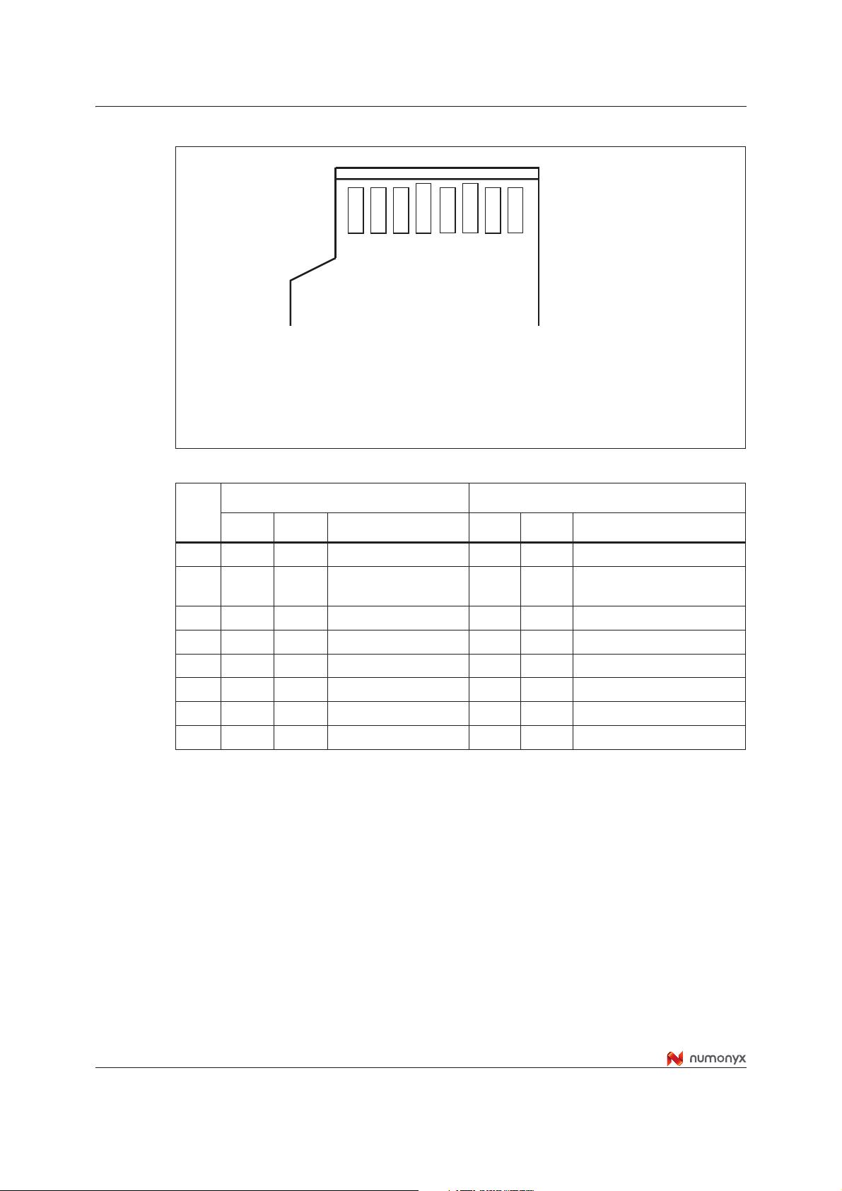
Figure 3. MicroSD pin assignment
Table 9. MicroSD Contact Pad Assignment
Pin
SD Mode SPI Mode
Name Type
(1)
1. S: power supply; I: input; O: output using push-pull drivers; PP: I/O using push-pull drivers.
Description Name Type Description
1 DAT2 I/O/PP Data Line [Bit 2] RSV Reserved
2
CD/DA
T3
(2)
2. The extended DAT lines (DAT1-DAT3) are input on power up. They start to operate as DAT lines after
SET_BUS_WIDTH command. The Host shall keep its own DAT1-DAT3 lines in input mode, as well, while
they are not used. It is defined so, in order to keep compatibility to MultiMediaCards.
I/O/PP
(3)
3. After power up this line is input with 50KOhm pull-up (can be used for card detection or SPI mode
selection). The pull-up should be disconnected by the user, during regular data transfer, with
SET_CLR_CARD_DETECT (ACMD42) command.
Card Detect / Data Line
[Bit 3]
CS I Chip Select (neg true)
3 CMD PP Command/Response DI I Data In
4 V
DD
S Supply voltage V
DD
S Supply voltage
5 CLK I Clock SCLK I Clock
6 V
SS
S Supply voltage ground V
SS
S Supply voltage ground
7 DAT0 I/O/PP Data Line [Bit 0] DO O/PP Data Out
8 DAT1 RSV Reserved
Ai11728
Pin 1
Pin 2
Pin 3
Pin 4
Pin 5
Pin 6
Pin 7
Pin 8


- 1
- 2
- 3
- 4
- 5
- 6
前往页