没有合适的资源?快使用搜索试试~ 我知道了~
Electronic Power Devices
需积分: 0 0 下载量 12 浏览量
2023-07-31
15:02:21
上传
评论
收藏 1.19MB PDF 举报
温馨提示
试读
13页
- Semiconductor modules and resistors on support plates are extremely sensitive to mechanical stress risk of breaking the ceramic insulation - Place the module onto the heat sink in correct position - Note the sequence of tightening the screws according to the type of module; initially use a very moderate torque to fix the module - Again observing the sequence of tightening the screws tighten them using the advised torque (refer to the given table)
资源推荐
资源详情
资源评论
Automation and DrivesAutomation and Drives
05_Power Electronics page 1
© Siemens Industry 2013 - subject to modification
Drive Technologies Division
Electronic
Power Devices
Automation and DrivesAutomation and Drives
05_Power Electronics page 2
© Siemens Industry 2013 - subject to modification
Drive Technologies Division
Table of Contents
Content Page
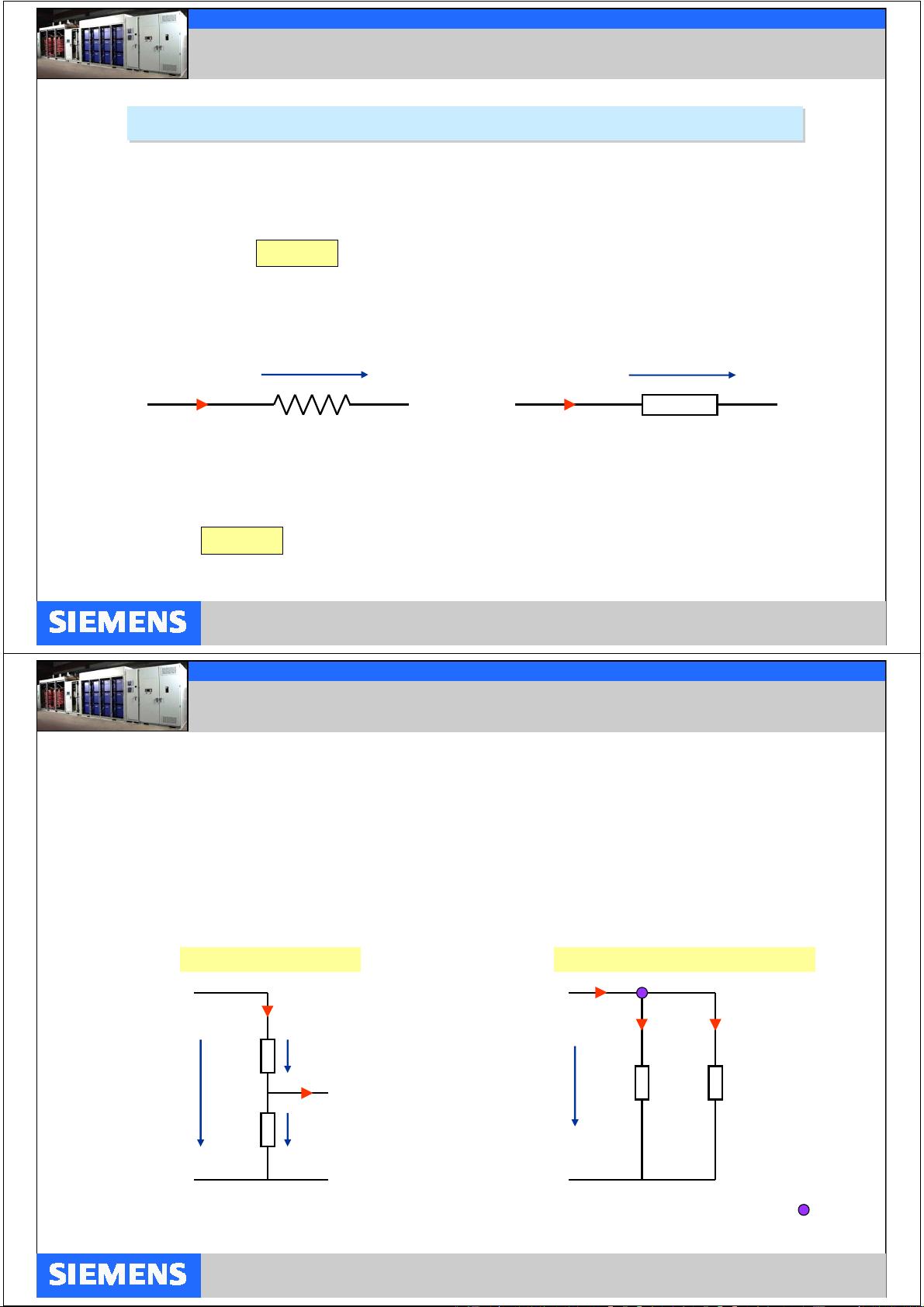
Resistor ...................................................................................................................................... 3
Resistors in Meshed Systems...................................................................................................... 4
Capacitor..................................................................................................................................... 5
Film Capacitor............................................................................................................................. 6
Dielectric Absorption.................................................................................................................... 7
Electrolytic Capacitor................................................................................................................... 8
Re-Forming................................................................................................................................. 9
Capacitors in DC- and AC-Circuits.............................................................................................. 10
Capacitors “in Series” and “in Parallel”........................................................................................ 11
Circuits with Resistors and Capacitors........................................................................................ 12
Inductor....................................................................................................................................... 13
Inductors in DC- and AC-Circuits / Application............................................................................ 14
Application of Inductors............................................................................................................... 15
Phase Angle between Voltage and Current in R-, C-, L-Circuits................................................. 16
Diode.......................................................................................................................................... 17
Application of Diodes in VFDs (Power Section).......................................................................... 18
SCR (Silicon Controlled Rectifier)............................................................................................... 19
Bipolar Transistor, Field Effect Transistor................................................................................... 20
IGBT........................................................................................................................................... 21
IGCT........................................................................................................................................... 22
Replacement of Power Devices.................................................................................................. 23
Diagnosing Power Cells.............................................................................................................. 24
Application of Thermal Joint Compound..................................................................................... 25
Fixing Semiconductor Modules................................................................................................... 26
Automation and DrivesAutomation and Drives
05_Power Electronics page 3
© Siemens Industry 2013 - subject to modification
Drive Technologies Division
Resistor
A resistor is a device which limits the current if voltage is applied across it.
The larger the resistance, the smaller the current for a given voltage.
Properties of resistors in circuits are same both for DC and for AC (high frequency excepted).
The physical quantity to specify the value of a resistor is called “Ohm”; the relation of resistance,
voltage and current is defined by “Ohm’s Law”:
R = v / i
or rearranged
i = v / R , v = i * R
Depending on the applied standard, different symbols are used for the resistor, different letters for the voltage.
voltage v [ V ]
resistor R
[ Ω ]
current i [ A ]
US standard
voltage u [ V ]
resistor R
[ Ω ]
current i [ A ]
SI standard
Current flow through a resistor results in electrical power which generates heat; the electrical
power is proportional to the product of voltage and current:
P = v * i
or redefined using Ohm’s Law
P = i
2
* R , P = v
2
/ R
Automation and DrivesAutomation and Drives
05_Power Electronics page 4
© Siemens Industry 2013 - subject to modification
Drive Technologies Division
The voltage applied on the series network is split
in same proportion as the resistor values; if both
resistors have same resistance, the voltage is
balanced symmetrically:
v1 / R1 = v2 / R2 v1 / v2 = R1 / R2
overall resistance: R
series
= R1 + R2
in general: R
series
= R
1
+ R
2
+ …. + R
n
The current fed to a parallel network is split in inverse
proportion to the resistor values; if both resistors have
same resistance, the current is
split symmetrically:
i1 * R1 = i2 * R2 i1 / i2 = R2 / R1
overall resistance: R
parallel
= (R1 * R2) / (R1 + R2)
in general: 1 / R
parallel
= 1 / R
1
+ 1 / R
2
+ …. + 1 / R
n
Resistors in Meshed Systems
Although resistors are mostly used in networks combined with other power devices they can also be found “by
themselves” either arranged “in series” or “in parallel”.
Connection “in series”
v1R1
i
R2 v2
v
i = 0
Rule: the sum of all voltages in a closed mesh
reads “zero”; e.g. v – v2 – v1 = 0 v = v1 + v2
Connection “in parallel”
Rule: the sum of all currents on a “current knot” ( )
reads “zero”; e.g. i – i1 – i2 = 0 i = i1 + i2
R1
i1
R2v
i2
i
Automation and DrivesAutomation and Drives
05_Power Electronics page 5
© Siemens Industry 2013 - subject to modification
Drive Technologies Division
The physical quantity to specify the value of a capacitor is called “Farad”; the relation of capacity,
voltage and electric charge [Q] is defined by:
Q = C * v
Capacitor
A capacitor is a device which stores an electric charge.
For a given capacity, the electric charge is directly proportional to the voltage.
A capacitor is a device which stores an electric charge.
For a given capacity, the electric charge is directly proportional to the voltage.
The larger the capacitor, the more electric charge is stored for a given voltage.
Depending on the applied standard, different symbols are used for the capacitor, different letters for the voltage.
US standard
SI standard
Properties of capacitors in circuits are different for DC and for AC.
film capacitor C
[ F ]
current i
[ A ]
film capacitor C
[ F ]
current i
[ A ]
voltage v [ V ]
electrolytic
capacitor C
[ F ]
voltage u [ V ]
electrolytic
capacitor C
[ F ]
Automation and DrivesAutomation and Drives
05_Power Electronics page 6
© Siemens Industry 2013 - subject to modification
Drive Technologies Division
The construction of a film capacitor is very
close to the ideal two plate model. A dielectric
(isolating material) separates two conductive
plates. For any dielectric with the dielectric
constant ε the capacitance is given by the area
A of the plates and the distance d (thickness of
the dielectric):
C = ε * A/d
Film Capacitor
Dielectric material and mechanical design will
depend on the application (voltage, pulse current,
temperature, high frequency losses etc.).
Typical dielectrics are for example:
Polystyrene (20 MV/m),
Polyethylene (22 MV/m),
waxed paper (60 MV/m),
PTFE or Teflon
®
(170 MV/m)
Polyester
Polycarbonate
Polyimide or Kapton
®
Maintenance: none
http://en.wikipedia.org
剩余12页未读,继续阅读
资源评论
vasya_petro
- 粉丝: 1
- 资源: 7
上传资源 快速赚钱
- 我的内容管理 展开
- 我的资源 快来上传第一个资源
- 我的收益 登录查看自己的收益
- 我的积分 登录查看自己的积分
- 我的C币 登录后查看C币余额
- 我的收藏
- 我的下载
- 下载帮助
安全验证
文档复制为VIP权益,开通VIP直接复制
信息提交成功