没有合适的资源?快使用搜索试试~ 我知道了~
Rsoft各个模块实例集合
1星 需积分: 48 87 下载量 91 浏览量
2018-03-05
19:12:15
上传
评论 6
收藏 62.06MB PDF 举报
温馨提示
试读
1022页
虽然原版实例集合容易找到,但是对于初学者而言,将各个模块的实例集合在一起学习很有用,更加方便。
资源推荐
资源详情
资源评论
BeamPROP 2013.12 83
7
Basic Tutorials
This chapter contains several basic tutorial examples which illustrate the basic use of the
BeamPROP simulation engine. These tutorials are increasingly complex and build on concepts
established in earlier tutorials. It is important that you perform them in order, even if a particular
topic is of most interest to you. It is also recommended that users work through the basic tutorials
in this chapter before moving to the advanced tutorials in Chapter 8.
These tutorials do not have associated design files.
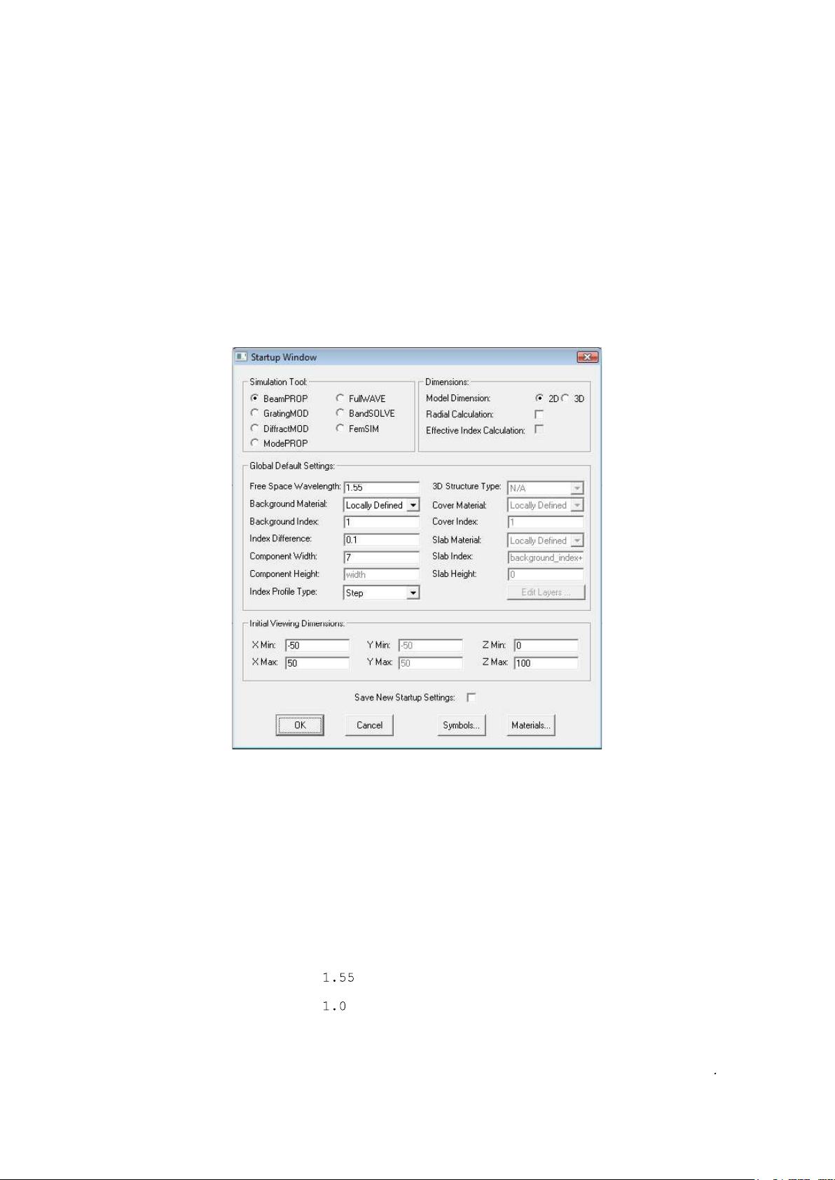
Basic Tutorial 1: Basic 2D Simulation
This tutorial illustrates basic CAD layout features by creating a new circuit and demonstrates a
sample workflow to perform a simulation and obtain simulation results. Our goal will be to
layout and simulate the propagation of a mode at 1.55 µm along a single 2D slab waveguide with
a cladding index of 1, a core index of 1.1, and a width of 7 µm. We will calculate the transmitted
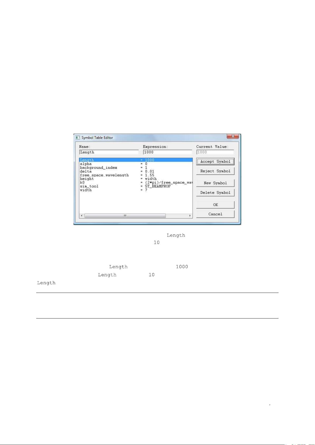
power along 1000 µm of this waveguide.
This tutorial will introduce basic concepts about the RSoft CAD interface and the BeamPROP
simulation engine that are critical for every user to understand; it is recommended that every new
user work through this tutorial. For additional information about the RSoft CAD, please consult
the CAD manual.
BeamPROP 2013.12 84
CAD Window Basics
We begin by opening up the RSoft CAD window. Windows users can do this via the Start menu
and Linux users can issue the command at a command prompt.
The CAD window, shown in Fig. 1, contains the following elements:
A menubar near the top of the window
The menubar allows access to various standard file and editing operations such as opening
and saving index files and cutting and pasting waveguide components in a circuit.
Two toolbars with icons just below the menubar
The top toolbars contain icons for standard file, editing, and viewing operations.
A toolbar along the left edge of the window
The left toolbar contains icons for standard CAD operations such as selection, zooming, and
adding different components. Additional icons control simulation and related aspects of the
program.
A status line at the bottom of the window
The status line provides information on the current layout mode, along with coordinate
display during drawing.
For a complete description of the functionality of the RSoft CAD interface, please see the CAD
manual.
Figure 1: The RSoft CAD program window, showing the menubar at the top, the top and left
toolbars, and the status line at the bottom.
BeamPROP 2013.12 85
Creating a New Circuit
To create a new circuit, click on the
New Circuit
icon in the top toolbar (the leftmost icon on the
top toolbar). The startup dialog appears, shown in Fig. 2, where basic information about the
circuit to be modeled is entered, including the wavelength of the light, the background refractive
index, the default index change between the background material and the structure, and the
approximate overall dimensions of the device.
Choosing Initial Settings:
Figure 2: The startup dialog which appears whenever a new circuit is created, and requests
basic information about the circuit to be modeled.
For this simulation, we will use the following settings:
Parameter Value Description
Simulation Tool
BeamPROP Sets BeamPROP
as the simulation engine to be
used.
Model Dimension
2D Creates a 2D simulation.
Free Space Wavelength
Sets the wavelength [µm] for the simulation.
Background Index
Represents the real refractive index of the
BeamPROP 2013.12 86
background material where no structure is
defined.
Index Difference
Represents the default difference between a
component and the background material. In
this case our structure will have a default i
ndex
of 1.1; each component can have a unique
value if desired.
Component Width
This sets the default width of a component
[µm];
each component can have a unique value
if desired.
Once these settings are made, click
OK
to continue. Note that changes can be made to these
the left CAD toolbar.
The Layout Window:
A layout window is created within the main CAD program window, as shown in Fig. 3. A coarse
coordinate grid is indicated by dots, and the X and Z axes are indicated by light gray lines. When
the mouse is moved into the layout window, the cursor becomes a cross-hair, and the coordinate
display in the status line indicates the mouse position in real coordinates [µm].
Figure 3: The layout window where waveguide components are added to the circuit.
BeamPROP 2013.12 87
Creating Variables via the Symbol Table
An important concept in the RSoft CAD is the Symbol Table. The Symbol Table allows the user
to create/modify both built-in and user-defined variables. These variables can be used to define
virtually any parameter within the CAD. Each symbol can be a function of any other symbol,
creating a parametric design environment.
The Symbol Table can be opened via the
Edit Symbols
icon in the CAD window. Figure 4
shows the symbol table for this design file which contains several symbols already defined that
correspond to the settings made in the startup dialog box above.
Figure 4: The Symbol Table Editor. The variable has been defined with a value of
.
In this tutorial, we are going to create a variable which will be used to set the length of our slab
waveguide. Define a symbol , and set it equal to . To do this, click
New Symbol
,
enter the symbol
Name
( ) and
Value
( ), and then click
Accept Symbol
. The variable
should now appear in the symbol table.
The names of symbols in the symbol table are case-sensitive. Also, symbols which begin with a
capital letter are displayed at the top of the list, and so it is recommended that any user-created
variables start with a capital letter so that they will be easier to find in the symbol table.
Adding the Waveguide
We can now add the waveguide structure to the CAD layout window.
Drawing the Waveguide:
The CAD has several convenient ways to add a component. For this tutorial we choose the
straight waveguide component, or
Segment Mode
, which has already been selected on the left
剩余1021页未读,继续阅读
资源评论
- asdfgju2020-04-11英文的 我看得懂???
tornadocgd
- 粉丝: 7
- 资源: 5
上传资源 快速赚钱
- 我的内容管理 展开
- 我的资源 快来上传第一个资源
- 我的收益 登录查看自己的收益
- 我的积分 登录查看自己的积分
- 我的C币 登录后查看C币余额
- 我的收藏
- 我的下载
- 下载帮助
安全验证
文档复制为VIP权益,开通VIP直接复制
信息提交成功