没有合适的资源?快使用搜索试试~ 我知道了~
Diagnostics with CAPL
需积分: 0 4 下载量 4 浏览量
2023-12-19
13:34:21
上传
评论
收藏 1.65MB PDF 举报
温馨提示
试读
28页
车载诊断样例,诊断配置。
资源推荐
资源详情
资源评论
Diagnostics with CAPL
2023-07-27
Support Note SN-IND-1-040
Author(s) Ernst, Oliver; Schwarz, Dirk
Restrictions Public Document
Copyright © 2022 – Vector Informatik GmbH 1
Contact Information: www.vector.com
Table of Contents
1 About this Support Note ............................................................................................................................... 2
2 Overview ....................................................................................................................................................... 2
3 Configuring the diagnostic components of CANoe/CANalyzer .................................................................... 2
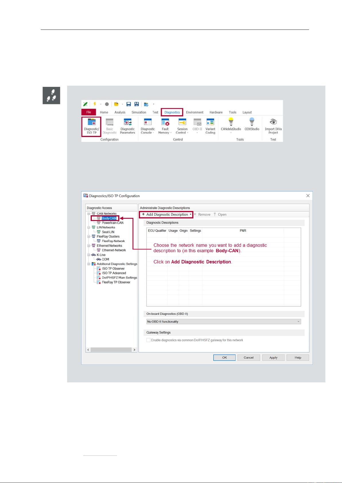
3.1 How to add a diagnostic description in CANoe/CANalyzer .................................................................. 3
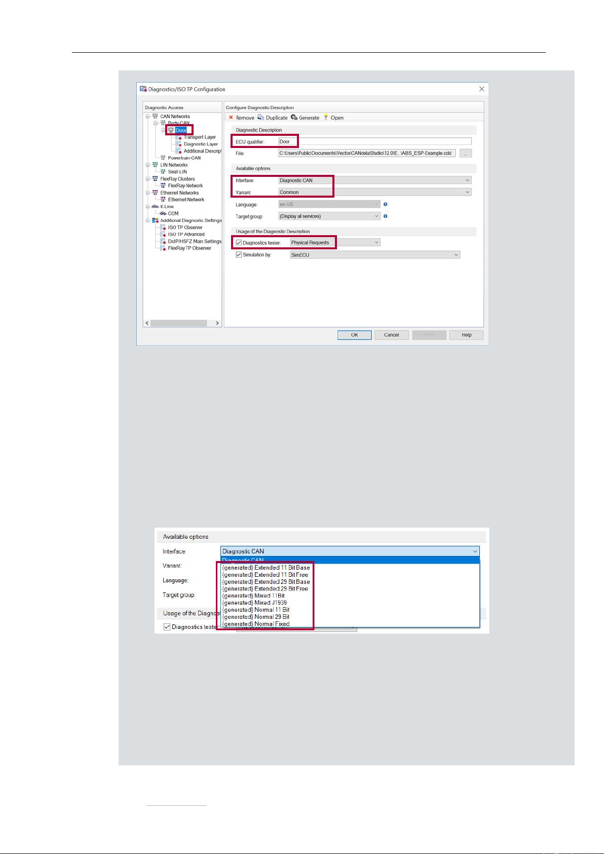
3.2 Property Pages ..................................................................................................................................... 5
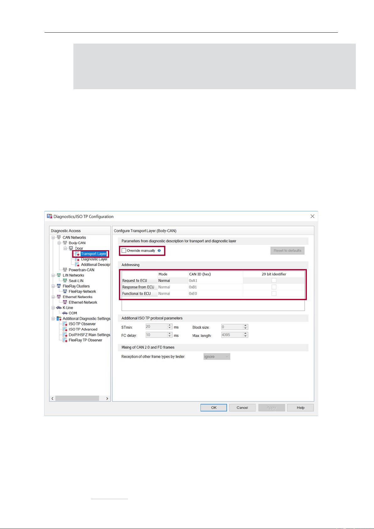
3.2.1 Transport Layer ............................................................................................................................ 5
3.2.2 Diagnostic Layer ........................................................................................................................... 6
3.2.3 Additional descriptions .................................................................................................................. 7
4 About qualifiers and short names ................................................................................................................. 8
5 Addressing the ECU ..................................................................................................................................... 9
6 Creating and sending a request ................................................................................................................... 9
7 Setting the parameters of a request ........................................................................................................... 10
8 Receiving the response and reading the response parameters ................................................................. 11
9 Reading the fault memory .......................................................................................................................... 13
10 Reading extended data records and snapshot data of the fault memory................................................... 14
11 Security access with Seed & Key DLL ....................................................................................................... 17
12 Diagnostics in test modules ........................................................................................................................ 19
13 Simulating an ECU ..................................................................................................................................... 21
14 Sending functional requests ....................................................................................................................... 24
15 Manipulating diagnostic data on raw level .................................................................................................. 25
16 Object-oriented programming ..................................................................................................................... 25
17 Where to find more information .................................................................................................................. 27
18 Contact information .................................................................................................................................... 28
Copyright © 2022 – Vector Informatik GmbH 2
Contact Information: www.vector.com
1 About this Support Note
In the table below you will find the icon conventions used throughout the Support Note.
Symbol
Utilization
This icon indicates notes and tips that facilitate your work.
This icon gives you step-by-step instructions.
This icon indicates examples.
2 Overview
This Support Note explains how to use the diagnostic functions provided by the CAPL programming language
in CANoe and in CANalyzer. Only diagnostics on CAN is covered, but aside from the bus specific aspects,
diagnostics on FlexRay, LIN, K-Line and DoIP is quite similar.
This Support Note is intended for CANoe versions starting from 9.0 SP3 and higher.
There is a separate Support Note for older CANoe versions. To receive it, please contact the Vector
Support (contact information in chapter 18).
All screenshots in this document are taken from CANoe 14.
3 Configuring the diagnostic components of CANoe/CANalyzer
If you want to create diagnostic tests or if you want to access the diagnostic data of an ECU with
CANoe/CANalyzer, you have to add a diagnostic description first. There are different types of descriptions
available:
> CDD (CANdela Diagnostic Description)
CDD files are created in the Vector tool CANdelaStudio.
> ODX (Open Diagnostic Data Exchange)
Since the diagnostic data can be divided into several ODX files, the description is usually provided as a
single PDX (packed ODX) file. A PDX can contain the diagnostic data for more than one ECU.
Therefore, you must select the ECU in this case.
> MDX (Multiplex Diagnostic Data Exchange)
This is an OEM-specific format.
If none of these concrete descriptions is available, CANoe/CANalyzer offers two alternatives:
> Standard Diagnostic Description
Predefined CDD files delivered with CANoe/CANalyzer which contain only services defined in the ISO
standards. The CDD files cannot be customized.
> Basic Diagnostic Description
This description must be created by the user inside CANoe/CANalyzer using the Basic Diagnostics
Editor.
Copyright © 2022 – Vector Informatik GmbH 3
Contact Information: www.vector.com
They have only limited functionality (e.g. Basic Diagnostic Descriptions do not contain a fault memory
model, session model or security access).
3.1 How to add a diagnostic description in CANoe/CANalyzer
> In the Diagnostics & XCP ribbon, click on Diagnostics/ISO-TP:
The Diagnostics/ISO TP Configuration window will appear.
> Choose the targeted network name and click on the button Add Diagnostic Description.
Select one diagnostic description type in the appearing drop-down menu and select the file
(except for basic diagnostics where the Basic Diagnostic Editor will open after closing this
dialog box).
After the selection of the diagnostic description, the diagnostic configuration for the chosen
network is available:
Copyright © 2022 – Vector Informatik GmbH 4
Contact Information: www.vector.com
The configuration`s branch is named after the ECU qualifier (here Door).
The most important settings are:
> ECU qualifier
The qualifier is a unique identifier for this diagnostic description.
It is also used in CAPL to address diagnostic requests (see chapter 5).
> Interface
The interface is a set of communication parameters to access the ECU.
In case the diagnostic description does not contain a valid or suitable set of these
parameters, you can use some default interfaces (prefixed with {generated}) for 11-bit and
29-bit addressing, for normal fixed addressing (for J1939), extended addressing, etc. see
screenshot below:
> Variant
The variant determines which services are available for diagnostics.
If the diagnostic description contains more than one variant, please choose the desired one
here.
> Diagnostics tester
Please determine which type of requests CANoe/CANalyzer as diagnostics tester should
use:
Copyright © 2022 – Vector Informatik GmbH 5
Contact Information: www.vector.com
> Physical Requests
The tester will send physical requests in order to access only one ECU on the network.
This is the typical way of diagnostic communication.
> Functional Group Requests
The tester will send functional requests in order to access all ECUs on the network.
3.2 Property Pages
The configuration’s branch has three property pages:
> Transport Layer
> Diagnostic Layer
> Additional Descriptions
The most important settings of these three pages are explained below.
3.2.1 Transport Layer
The settings on this page depend on the bus type. For CAN it looks like this:
> Override manually
You can decide whether to use the communication parameters of the selected interface or to overwrite
them and use different values. Depending on the addressing method (physical or functional requests)
some or all of these parameters on this page are editable. If you have selected one of the default
interfaces (prefixed with {generated}), the override manually setting is automatically checked as you
are required to make some settings (e.g. like CAN ID).
剩余27页未读,继续阅读
资源评论
sinwintter
- 粉丝: 0
- 资源: 1
上传资源 快速赚钱
- 我的内容管理 展开
- 我的资源 快来上传第一个资源
- 我的收益 登录查看自己的收益
- 我的积分 登录查看自己的积分
- 我的C币 登录后查看C币余额
- 我的收藏
- 我的下载
- 下载帮助
安全验证
文档复制为VIP权益,开通VIP直接复制
信息提交成功