没有合适的资源?快使用搜索试试~ 我知道了~
Hierarchical error model toestimate motion error .pdf
需积分: 5 0 下载量 18 浏览量
2022-04-25
00:57:10
上传
评论
收藏 1.53MB PDF 举报
温馨提示
试读
13页
Hierarchical error model toestimate motion error .pdf
资源详情
资源评论
资源推荐
ORIGINAL ARTICLE
Hierarchical error model to estimate motion error of linear
motion bearing table
Gaiyun He
1
& Guangming Sun
1
& Heshuai Zhang
1
& Can Huang
1
& Dawei Zhang
1
Received: 18 February 2017 /Accepted: 5 June 2017 / Published online: 23 June 2017
#
Springer-Verlag London Ltd. 2017
Abstract This study presents a general and systematic ap-
proach for motion error estimation of a linear motion bearing
table based on hierarchical idea. The approach is implemented
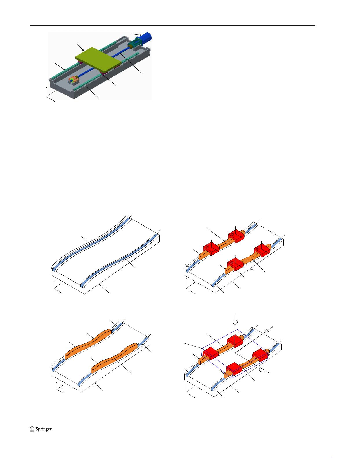
in the following four steps: (1) dividing the errors of a linear
motion system into four tiers, namely Datum Tier, Guideway
Tier, Slider Tier, and Table Tier; (2) measuring form errors of
Guideway Tier using the proposed method that combines the
displacement sensors and laser interferometer; (3) developing
a map of the form errors of Guideway Tier and motion errors
of Slider Tier using the Hertz contact theory and a transfer
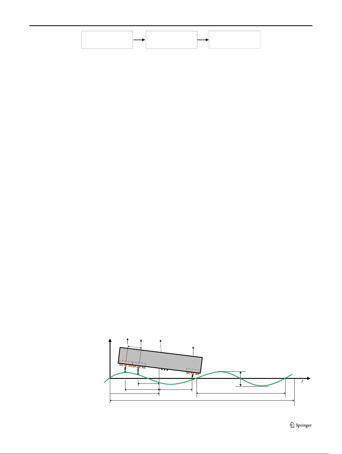
function method; and (4) formulating a map between the mo-
tion errors of Slider Tier and the error of Table Tier using a
direction cosine matrix. The advantage of this approach is that
it does not require the assumption that the form error phases of
the two guide rails are the same, and thereby provides a more
accurate model of motion error. A typical linear motion bear-
ing table is considered as an example to illustrate the general-
ity and effectiveness of the proposed approach.
Keywords Hierarchical error model
.
Linear motion bearing
table
.
Rail form error
.
Motion error
1 Introduction
W ith the progress of industrial development, numerical control
machine tools, as material carriers of advanced manufacturing
technology, are widely used in machining manufacturing [1–7].
Linear motion bearing tables are importa nt part of a machine tool
and play a crucial role there in owing to their high positioning
accuracy and carrying capacity [8–11]. The motion error of a
linear motion bearing table is mainly affected by guideway form
error , and this has a direct influence on the accuracy of the ma-
chined parts [12]. Therefore, an accurate model is essential to
estimate the error of a linear motion bearing table in the design
and manufacturing process. This, in turn , will allow the adoption
of suitable measures to improve the accuracy via component
tolerance design, manufacturing, and assembly techniques.
Over the past few decades, a considerable amount of inten-
sive research has focused on estimating the error of a linear
motion bearing table. Díaz-Tena et al. developed a methodol-
ogy for the assessment of the geometrical accuracy of a multi-
axis machine based on the D–Hmethod[13]. Majda proposed
a model for rolling guideways with geometric errors and con-
sidered aspects of the practical use of the characteristics of
joint kinematic errors in models for volumetric error in a
medium-sized machine tool [14]. Zha et al. studied motion
straightness of hydrostatic guideways by considering the ratio
of pad center spacing to guide rail profile error wavelengths
[15]. Shamoto et al. proposed a transfer function method to
develop a map of the guideway form errors and table motion
errors and verified its effectiveness through an experiment
[16]. However, the study only focused on the motion error
of a table in a two-dimensional plane [17, 18]. Based on this,
Khim et al. presented a model that extended the motion errors
of the aforementioned study to a three-dimensional space by
using a transfer function method. However, this study did not
consider guide parallelism [19]. Kim et al. proposed an im-
proved transfer function method that accounted for the guide-
way parallelism error in the prediction motion errors of the
table [20]. However, this model assumed that the phase and
amplitude of form errors of different guide rails were the same,
and this is evidently different from the actual conditions. Thus,
* Gaiyun He
hegaiyun@tju.edu.cn
1
Key Laboratory of Mechanism Theory and Equipment Design of
Ministry of Education, Tianjin University, Tianjin 300072, China
Int J Adv Manuf Technol (2017) 93:1915–1927
DOI 10.1007/s00170-017-0635-0
it is necessary to construct more effective models that consider
the actual conditions.
It is necessary to measure the form error of the guideways
to estimate the motion error. Tanaka et al. proposed a sequen-
tial two-point method to measure the form error of hydrostatic
guideways [21, 22]. Hwang et al. designed a three-probe sys-
tem that was used to measure the straightness and parallelism
error of horizontal guideways and verified the effectiveness
and accuracy of the proposed system through theoretical
analysis and experiments [23]. Khim et al. applied this method
to measure the form error of hydrostatic guideways [19].
Based on the study, Kim et al. designed a porous aerostatic
bearing stage and adopted a sequential multi-point method to
perform measurements [20]. Previous studies proposed sever-
al methods to measure the form error of guideways. However,
these methods require special measuring devices that can only
be applied to a particular motion system and involve signifi-
cant expense. A universal measuring method that measures
the form error of guideways economically and does not re-
quire any special device is necessary.
This study presents a hierarchical error model for motion
error estimation of a linear motion bearing table and proposes
a universal measuring method for form error measurement.
Section 1 briefly addresses the current challenges in error
modeling of a linear motion guide system. Section 2 intro-
duces the hierarchical error model for a linear motion bearing
table and establishes a new systematic model. In this model,
the map of form errors of the Guideway Tier and motion errors
of the Slider Tier is first formulated using Hertz contact theory
and the transfer function method. Subsequently, the map of
the motion errors of the Slider Tier a nd the errors of the
Guide
Machine bed
Motor
Table
Ball screw
Slider
x
z
y
o
Fig. 1 Linear motion bearing table
(a)
Machine bed
Datum2
Guide2
x
z
y
o
e01(x)
e02(x)
Datum1
e11(x)
e12(x)
Guide1
(b)
Machine bed
Datum2
Guide2
x
z
y
o
Slider
e11(x)
e12(x)
e01(x)
e02(x)
Y11(x)
Guide1
Y21(x)
Y12(x)
Y22(x)
Datum1
Z22(x)
Z12(x)
Z11(x)
Z21(x)
(c)
Machine bed
Datum2
Guide2
Table
x
z
y
o
EYX
e11(x)
e12(x)
e01(x)
e02(x)
Guide1
Datum1
EZX
EAX
EBX
ECX
EXX
(d)
Datum2
Machine bed
x
z
o
y
Datum1
e01(x)
e02(x)
Fig. 2 Schematic diagram of the four tiers. a Datum Tier. b Guideway Tier. c Slider Tier. d Table Tier
1916 Int J Adv Manuf T echnol (2017) 93:1915–1927
Table Tier is formulated using the direction cosine matrix. A
universal measuring method of form errors is introduced in
Sect. 3. In Sect. 4, a typical linear motion bearing table is
considered as an example to illustrate the generality and effec-
tiveness of the proposed approach. The conclusions are
discussed in Sect. 5.
2 Hierarchical error model
A linear motion bearing table is powered by rotary motors via
a ball screw and nut assembly and is mainly composed of bed,
guide, slider, and table as shown in Fig. 1.
Based on the assembly sequence, the erro rs of a linear
motion system can be divided into four tiers, namely Datum
Tier, Guideway Tier, Slider Tier, and Table Tier as shown in
Fig. 2. In Datum Tier, the form errors of two datum planes are
manufactured on the bed and t heir main err ors include
straightness e
01
(x)ande
02
(x) as shown in Fig. 2 a. In
Guideway Tier, two guideways are installed on the datum
plane of the bed. The factor influencing the rail form errors
e
11
(x)ande
12
(x) follows thereafter as a result of the following
two main aspects: manufacturing error of the guide rail and
elastic deformation due to datum errors and installation torque
as shown in Fig. 2b. In Slider Tier, two sliders are mounted on
each guideway, and the motion error of the slider is affected by
the contact conditions between the rail form error and rolling
element as shown in Fig. 2c. This is ex pressed as Z
11
(x),
Z
12
(x), Z
21
(x), and Z
22
(x)intheZ direction and Y
11
(x),
Y
12
(x), Y
21
(x), and Y
22
(x) in the Y direction. In Table Tier,
the table is supported by four sliders, and its motion errors
E
YX
, E
ZX
, E
AX
, E
BX
,andE
CX
[24] are determined by the four
sliders as shown in Fig. 2d. E
YX
and E
ZX
denote the straight-
ness error motion in the Y-axis and Z-axis directions (E
XX
denotes the linear positioning error motion of the X-axis, and
it is determined by the numerical control system), whereas
E
AX
, E
BX
,andE
CX
correspond to angular error motion around
the A-axis (roll), B-axis (yaw), and C-axis (pitch).
The motion error is calculated tier by tier in the hierarchical
error model. It is difficult to build a precise mathematical
model in the map of the datum errors to the guide rail errors
due to its complexity, nonlinearity, and uncertainty; thus, this
is beyond the scope of the present study. The rail form errors
are measured by using displacement sensors and a laser inter-
ferometer. The motion errors of Slider Tier can be presented
by mathematical models that are combined with the Hertz
contact theory and the transfer function. The motion errors
of Table Tier are affected by Slider Tier and are calculated
using the direction cosine matrix and a homogeneous coordi-
nate transformation. The f low chart of hierarchical error
modeling is shown in Fig. 3. The advantage of this approach
is that it does not require an assumption that the phase and
amplitude of the form errors of the two guide rails are the
same.
2.1 Error modeling of the Slider Tier
During the movement of the slider, the bearing force varies
with respect to the rail form error. To analyze the motion error
of slider, the following assumptions are involved in the model-
ing process:
1. The guideway and slider are considered as rigid parts, and
the balls are considered as elastic bodies.
2. The form error exists only on the guide rail.
3. The form error of the guideway has a continuous profile
and can be represented as a periodic function.
Calculate motion error of
slider tier
(), ()
ij ij
YxZ x
Calculate motion error of
table tier
,, ,,
ZX YX AX BX CX
EEEEE
Measure rail
form error
,,
(), ()
Ljk Rjk
exex
Fig. 3 Flow chart of hierarchical error modeling
y
O
e(x)
X
1
X
2
x
X
m
L
O
l
Y
1
(x)
Y
2
(x)
E
YX
Y
m
(x)
f
ey2
(x)
f
eym
(x)
λ
2δ
x
K(0)
K(0)
K(0)
f
ey1
(x)
Fig. 4 Model of a slider for
motion error analysis
Int J Adv Manuf Technol (2017) 93:1915–1927 1917
剩余12页未读,继续阅读
qq_57867739
- 粉丝: 0
- 资源: 1
上传资源 快速赚钱
- 我的内容管理 展开
- 我的资源 快来上传第一个资源
- 我的收益 登录查看自己的收益
- 我的积分 登录查看自己的积分
- 我的C币 登录后查看C币余额
- 我的收藏
- 我的下载
- 下载帮助
安全验证
文档复制为VIP权益,开通VIP直接复制
信息提交成功
评论0