没有合适的资源?快使用搜索试试~ 我知道了~
TI 毫米波雷达 - DCA1000 ADC 原始数据解析源码分享
2 下载量 163 浏览量
2024-05-14
23:21:53
上传
评论 1
收藏 1.58MB PDF 举报
温馨提示
试读
23页
TI 毫米波雷达 - DCA1000 ADC 原始数据解析源码分享
资源推荐
资源详情
资源评论
1
SWRA581B–December 2017–Revised October 2018
Submit Documentation Feedback
Copyright © 2017–2018, Texas Instruments Incorporated
Mmwave Radar Device ADC Raw Data Capture
Application Report
SWRA581B–December 2017–Revised October 2018
Mmwave Radar Device ADC Raw Data Capture
ABSTRACT
This application report demonstrates how to interpret raw analog-to-digital converter (ADC) data that is
captured using the Capture Demo or Mmwave Studio. The format of captured raw ADC data is discussed
for different hardware setup respectively. Matlab snippet is provided for engineers who need to develop
custom code for data processing.
Contents
1 Introduction ................................................................................................................... 2
2 Prerequisites.................................................................................................................. 3
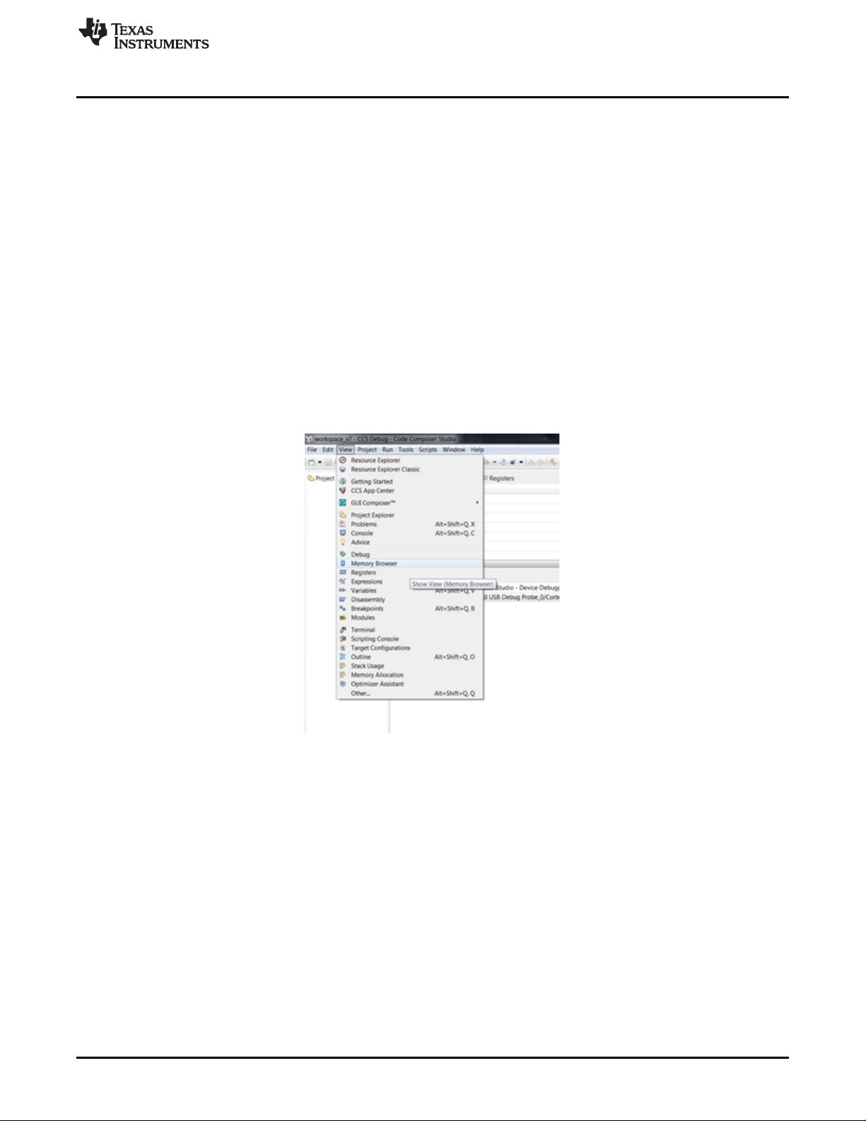
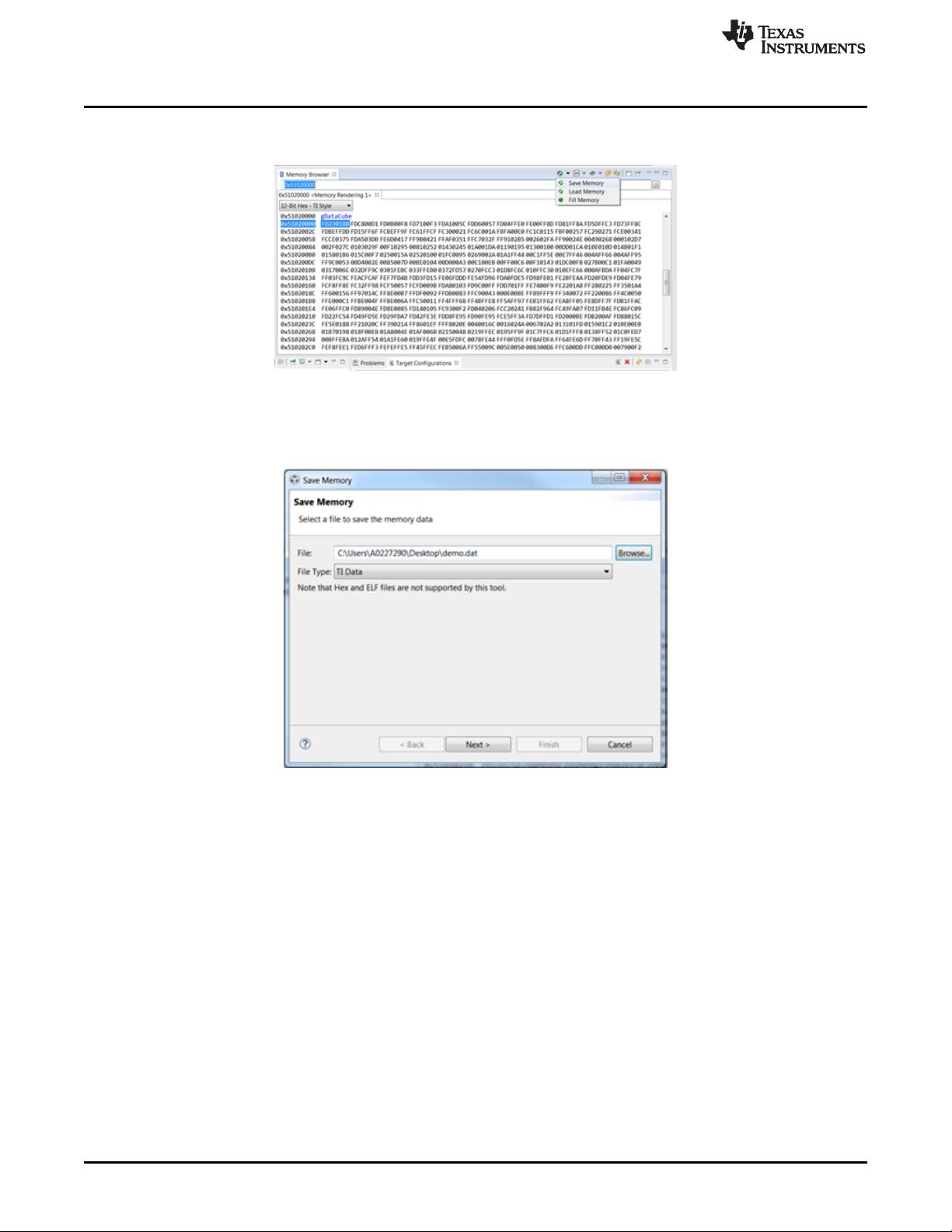
3 Viewing and Saving Raw Data Using Capture Demo and CCS....................................................... 3
4 Raw Data Format of Capture Demo Using CCS ........................................................................ 5
5 xWR12xx and xWR14xx With DCA1000 Data Format ................................................................. 7
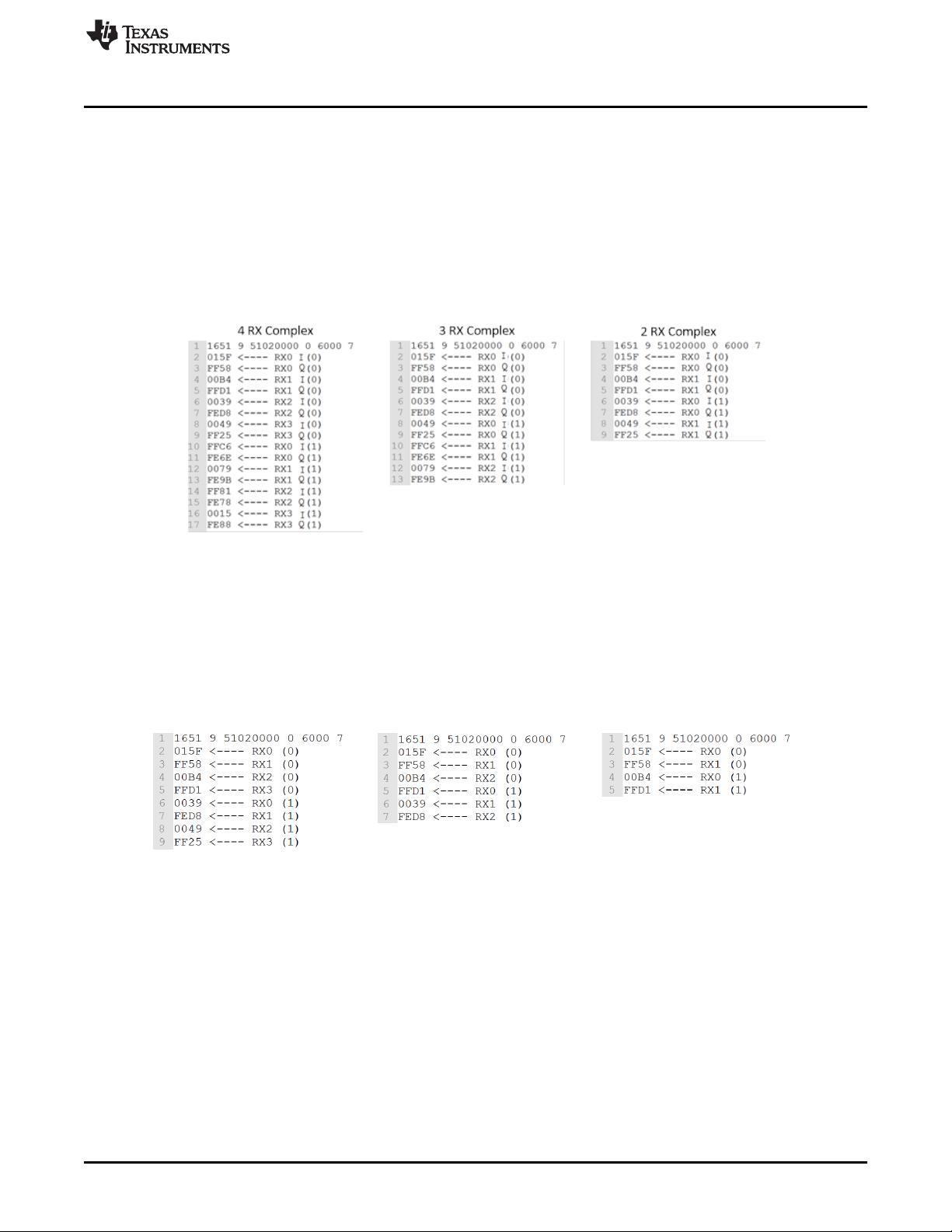
6 xWR16xx and IWR6843 With DCA1000 Data Format ................................................................. 9
7 xWR12xx and xWR14xx With TSW1400 Data Format................................................................ 11
8 xWR16xx and IWR6843 With TSW1400 Data Format ................................................................ 13
9 Interpreting Binary File in MATLAB ...................................................................................... 15
10 Summary .................................................................................................................... 21
11 References .................................................................................................................. 21
List of Figures
1 Opening Memory Browser in CCS ........................................................................................ 3
2 Memory Browser Save Memory Button................................................................................... 4
3 Save Memory and File Type ............................................................................................... 4
4 Interleaved Complex Data Format Using Capture Demo .............................................................. 5
5 Interleaved Real Data Format Using Capture Demo ................................................................... 5
6 Non-Interleaved Complex Data Format Using Capture Demo......................................................... 6
7 Non-Interleaved Real Data Format Using Capture Demo.............................................................. 6
8 xWR14xx Real Data Format Using DCA1000 ........................................................................... 7
9 xWR14xx Complex Data Format Using DCA1000 ...................................................................... 8
10 xWR16xx/IWR6843 Real Data Format Using DCA1000 ............................................................... 9
11 xWR16xx/IWR6843 Complex Data Format Using DCA1000......................................................... 10
12 xWR14xx Real Data Format Using TSW1400 ......................................................................... 11
13 xWR14xx Complex Data Format Using TSW1400 .................................................................... 12
14 xWR16xx/IWR6843 Real Data Format for One Receiver Using TSW1400 ........................................ 13
15 xWR16xx/IWR6843 Real Data Format for Multiple Receivers Using TSW1400................................... 13
16 xWR16xx/IWR6843 Complex Data Format Using TSW1400 ........................................................ 14
17 MATLAB Script Output -- xWR14xx With DCA1000................................................................... 16
18 MATLAB Script Output -- xWR16xx With DCA1000................................................................... 17
19 MATLAB Script Output -- xWR14xx With TSW1400 .................................................................. 19
20 MATLAB Script Output -- xWR16xx With TSW1400 .................................................................. 20
Introduction
www.ti.com
2
SWRA581B–December 2017–Revised October 2018
Submit Documentation Feedback
Copyright © 2017–2018, Texas Instruments Incorporated
Mmwave Radar Device ADC Raw Data Capture
Trademarks
Code Composer Studio is a trademark of Texas Instruments.
All other trademarks are the property of their respective owners.
1 Introduction
The raw data of the mmwave radar (xWRxxxx) can be captured using the Capture Demo provided in the
mmWave SDK, or using Mmwave Studio provided in Mmwave Studio GUI tools. The primary topics
covered include how to save raw data from the Capture Demo using Code Composer Studio™ (CCS), the
raw data format of data captured using the Capture Demo, the raw data format of data captured using
Mmwave Studio, and how to interpret the data in MATLAB. This document assumes that the user knows
how to run the Capture Demo and Mmwave Studio. For instructions on how to run the Capture Demo,
consult the mmWave SDK Demo Setup Guide found in the TI Resource Explorer mmWave Training
Demos folder. For information on how to capture data using Mmwave Studio, consult the Mmwave Studio
User's Guide in Mmwave Studio GUI tools.
Note that Mmwave Studio, previously known as Radar Studio, supports two different platforms. One is
DCA1000EVM Data Capture Card User's Guide, which has interface with xWRxxxx EVM that enables
users to stream the ADC data over Ethernet. Another platform is TSW140x High Speed Data
Capture/Pattern Generator Card which requires Mmwave devPack EVM and High Speed Data Converter
Pro GUI User's Guide. TSW1400 EVM transmits the captured data through Serial Peripheral Interface
(SPI) to PC (through onboard USB to SPI converter). The Radar Studio (older version of Mmwave Studio)
only supports TSW1400 EVM with HSDC Pro. For more information, see Device Firmware Package for
the Radar Studio User's Guide and mmWave Sensor Raw Data Capture Using the TSW1400 Board for
the training video.
For differences in the user interface of Mmwave Studio for DCA1000 EVM and TSW1400, see the
Mmwave Studio User Guide . DCA1000 design is based on Lattice FPGA and LVDS data is captured
through Ethernet streaming. TSW1400 EVM, based on Altera FPGA, capture the LVDS data in different
format. Data format also depends on the type of mmwave devices. Therefore, the different format need to
be discussed separately.
The application report is organized as follows - Section 2 lists the prerequisites. Section 3 describes how
to run and save ADC data using capture demo and CCS. Section 4 discusses the data format saved by
capture demo and CCS. Section 5,Section 6,Section 7 and Section 8 have detailed description of the data
format saved by Mmwave Studio for different xWRxxxx devices using DCA1000 and TSW1400,
respectively. Section 9 provides Matlab script example to process the data captured by Mmwave Studio.
www.ti.com
Prerequisites
3
SWRA581B–December 2017–Revised October 2018
Submit Documentation Feedback
Copyright © 2017–2018, Texas Instruments Incorporated
Mmwave Radar Device ADC Raw Data Capture
2 Prerequisites
This document assumes that the user has installed the necessary prerequisites for the Capture Demo,
Mmwave Studio and is familiar with the instructions on how to use this software. This document has been
tested against SDK 1.01.00.02, CCSv7.3, Mmwave Studio 1.0.0.0.
For information on how to run the Capture Demo and any necessary prerequisites, install the mmWave
SDK. Also see the mmWave SDK User’s Guide, found at C:\ti\mmwave_sdk_<version_number>\docs.
For information on how to run Mmwave Studio and any necessary prerequisites, install Mmwave Studio
GUI tools. Also see the Mmwave Studio User’s Guide, found at
C:\ti\mmwave_studio_<version_number>\docs
3 Viewing and Saving Raw Data Using Capture Demo and CCS
This section discusses how to view and save the raw ADC data captured using the Capture Demo
provided in the mmWave SDK. This section assumes that the user is familiar with how to run the Capture
Demo using CCS. For information on how to run the Capture Demo, consult the mmWave SDK User’s
Guide , found at C:\ti\mmwave_sdk_<version_number>\docs.
The ADC data is stored in L3 can be viewed and saved using the Memory Browser in CCS. To access the
Memory Browser, open the View tab and select the Memory Browser option, shown in Figure 1.
Figure 1. Opening Memory Browser in CCS
In the Memory Browser window, the contents of the L3 memory can be viewed by specifying the start
address of the L3 memory. The start address is specified by CAPTURE_L3RAM_DATA_MEM_ADDRESS
in the capture.h file and varies based on SDK version. The total size of memory reserved to store ADC
data is specified by CAPTURE_L3RAM_DATA_MEM_SIZE in capture.h. Additionally, the L3 address and
size are output in the last line of the CCS console before sending the configuration file to the device.
Viewing and Saving Raw Data Using Capture Demo and CCS
www.ti.com
4
SWRA581B–December 2017–Revised October 2018
Submit Documentation Feedback
Copyright © 2017–2018, Texas Instruments Incorporated
Mmwave Radar Device ADC Raw Data Capture
To save the raw ADC data click the Save Memory button at the top right corner of the Memory Browser
window as shown in Figure 2.
Figure 2. Memory Browser Save Memory Button
In the Save Memory menu, specify the file path and file name and select TI Data as the file type as shown
in Figure 3.
Figure 3. Save Memory and File Type
Click Next and specify the format, start address and length. For the format, select 16-Bit Hex – TI Style.
The length of the data is based on the users chirp configuration. To calculate the length in words, the
following formulas can be used. First, find the total size of ADC data generated in bytes.
Total Size in Bytes = Num ADC Samples × Num RX Channels × Num Frames × Num Chirps × Num Bytes Per
Sample (1)
The number of bytes per sample is based the output format specified by the adcCfg parameter in the
sensor configuration. For a complex output format, there are 4 bytes per sample: 2 bytes for the real part
and 2 bytes for the imaginary part. For a real output format, there are 2 bytes per sample. Once the total
size of the data in bytes is determined the number of words can be found by dividing the total size by 16;
this assumes that the user is saving in a 16-bit Hex – TI Style format.
Length in Words = Total Size / 2 bytes per word (2)
Once the data is saved, it can be viewed in MATLAB using the capture_demo.m file located at
C:\mmwave_sdk_<version_number>\packages\ti\demo\xwr14xx\capture\gui for the xWR1xx, and located
at C:\ti\mmwave_sdk_01_00_00_05\packages\ti\demo\xwr16xx\capture\gui for the xWR16xx. This file
plots the raw ADC data and the 1D FFT of the ADC data. This code can be modified to complete
additional post processing on the data. To do further post processing, you must understand how the
output data is formatted, as shown in Section 4.
4 RX Real 3 RX Real 2 RX Real
www.ti.com
Raw Data Format of Capture Demo Using CCS
5
SWRA581B–December 2017–Revised October 2018
Submit Documentation Feedback
Copyright © 2017–2018, Texas Instruments Incorporated
Mmwave Radar Device ADC Raw Data Capture
4 Raw Data Format of Capture Demo Using CCS
Data captured using the Capture Demo can be stored in interleaved or non-interleaved mode, as specified
by the adcbufCfg command in the sensor configuration. For xWR14xx devices, interleaved mode is
recommended but non-interleaved mode can also be used. For xWR16xx/IWR6843 devices only non-
interleaved mode can be used. By default the xWR14xx is configured for interleaved mode and the
xWR16xx/IWR6843 is configured for non-interleaved mode. For more information about interleaving, see
the AWR1xxx Data Path Programmer's Guide programmer’s guide. Data is stored in a 16-bit, two's-
complement format.
Figure 4 shows the output data for interleaved mode with complex data for 4 RX, 3 RX, and 2 RX
antennas..
Figure 4. Interleaved Complex Data Format Using Capture Demo
Figure 4 represents how the data is saved when using 16-bit Hex – TI Style when the file is saved as a TI
data format file. In Figure 4, RX0 I(0) represents the first sample of real data received at RX0, and RX0
Q(0) represents the first sample of imaginary data received at RX0. RX0 I(1) represents the second
sample of real data received at RX0, and so on.
Data can also be captured as real data only. Figure 5 shows how the data is saved for interleaved mode
with real data for 4 RX, 3 RX, and 2 RX antennas.
Figure 5. Interleaved Real Data Format Using Capture Demo
剩余22页未读,继续阅读
资源评论
雷达爆破手
- 粉丝: 191
- 资源: 38
上传资源 快速赚钱
- 我的内容管理 展开
- 我的资源 快来上传第一个资源
- 我的收益 登录查看自己的收益
- 我的积分 登录查看自己的积分
- 我的C币 登录后查看C币余额
- 我的收藏
- 我的下载
- 下载帮助
安全验证
文档复制为VIP权益,开通VIP直接复制
信息提交成功