没有合适的资源?快使用搜索试试~ 我知道了~
2Gb-DDR3-MT41K128M16.pdf
需积分: 0 0 下载量 187 浏览量
2024-03-28
17:01:47
上传
评论
收藏 561KB PDF 举报
温馨提示
试读
29页
2Gb-DDR3-MT41K128M16.pdf
资源推荐
资源详情
资源评论
1.35V DDR3L SDRAM
MT41K512M4 – 64 Meg x 4 x 8 banks
MT41K256M8 – 32 Meg x 8 x 8 banks
MT41K128M16 – 16 Meg x 16 x 8 banks
Description
The 1.35V DDR3L SDRAM device is a low-voltage ver-
sion of the 1.5V DDR3 SDRAM device. Unless stated
otherwise, the DDR3L SDRAM device meets the func-
tional and timing specifications listed in the equiva-
lent density standard or automotive DDR3 SDRAM
data sheet located on www.micron.com.
Features
• V
DD
= V
DDQ
= 1.35V (1.283–1.45V)
• Backward-compatible to V
DD
= V
DDQ
= 1.5V ±0.075V
• Differential bidirectional data strobe
• 8n-bit prefetch architecture
• Differential clock inputs (CK, CK#)
• 8 internal banks
• Nominal and dynamic on-die termination (ODT)
for data, strobe, and mask signals
• Programmable CAS (READ) latency (CL)
• Programmable posted CAS additive latency (AL)
• Programmable CAS (WRITE) latency (CWL)
• Fixed burst length (BL) of 8 and burst chop (BC) of 4
(via the mode register set [MRS])
• Selectable BC4 or BL8 on-the-fly (OTF)
• Self refresh mode
• T
C
of 0°C to +95°C
– 64ms, 8192-cycle refresh at 0°C to +85°C
– 32ms at +85°C to +95°C
• Self refresh temperature (SRT)
• Automatic self refresh (ASR)
• Write leveling
• Multipurpose register
• Output driver calibration
Options Marking
• Configuration
– 512 Meg x 4 512M4
– 256 Meg x 8 256M8
– 128 Meg x 16 128M16
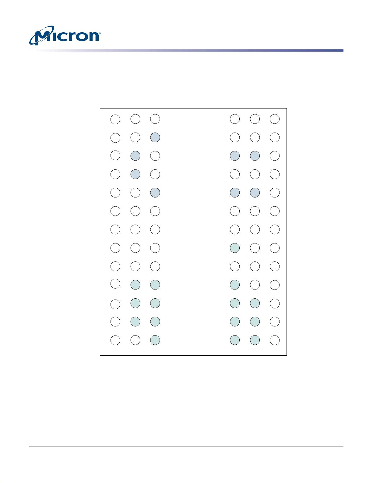
• FBGA package (Pb-free) – x4, x8
– 78-ball (8mm x 10.5mm)
Rev. H, M, K
DA
– 78-ball FBGA (9mm x 11.5mm)
Rev. D
HX
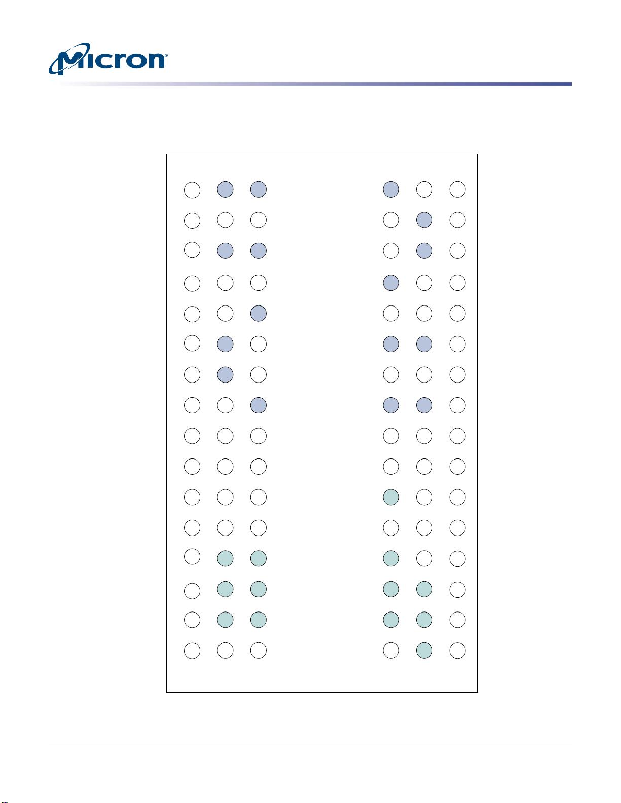
• FBGA package (Pb-free) – x16
– 96-ball FBGA (9mm x 14mm)
Rev. D
HA
– 96-ball FBGA (8mm x 14mm)
Rev. K
JT
• Timing – cycle time
– 1.071ns @ CL = 13 (DDR3-1866) -107
– 1.25ns @ CL = 11 (DDR3-1600) -125
– 1.5ns @ CL = 9 (DDR3-1333) -15E
– 1.875ns @ CL = 7 (DDR3-1066) -187E
• Operating temperature
– Commercial (0°C ≤ T
C
≤ +95°C) None
– Industrial (–40°C ≤ T
C
≤ +95°C) IT
• Revision :D/ :H/ :K/ :M
Table 1: Key Timing Parameters
Speed Grade Data Rate (MT/s) Target
t
RCD-
t
RP-CL
t
RCD (ns)
t
RP (ns) CL (ns)
-107
1, 2, 3
1866 13-13-13 13.91 13.91 13.91
-125
1, 2
1600 11-11-11 13.75 13.75 13.75
-15E
1
1333 9-9-9 13.5 13.5 13.5
-187E 1066 7-7-7 13.1 13.1 13.1
Notes:
1. Backward compatible to 1066, CL = 7 (-187E).
2. Backward compatible to 1333, CL = 9 (-15E).
3. Backward compatible to 1600, CL = 11 (-107).
2Gb: x4, x8, x16 DDR3L SDRAM
Description
PDF: 09005aef83ed2952
2Gb_1_35V_DDR3L.pdf - Rev. I 10/12 EN
1
Micron Technology, Inc. reserves the right to change products or specifications without notice.
© 2010 Micron Technology, Inc. All rights reserved.
Products and specifications discussed herein are subject to change by Micron without notice.
Table 2: Addressing
Parameter 512 Meg x 4 256 Meg x 8 128 Meg x 16
Configuration 64 Meg x 4 x 8 banks 32 Meg x 8 x 8 banks 16 Meg x 16 x 8 banks
Refresh count 8K 8K 8K
Row address 32K A[14:0] 32K A[14:0] 16K A[13:0]
Bank address 8 BA[2:0] 8 BA[2:0] 8 BA[2:0]
Column address 2K A[11, 9:0] 1K A[9:0] 1K A[9:0]
2Gb: x4, x8, x16 DDR3L SDRAM
Description
PDF: 09005aef83ed2952
2Gb_1_35V_DDR3L.pdf - Rev. I 10/12 EN
2
Micron Technology, Inc. reserves the right to change products or specifications without notice.
© 2010 Micron Technology, Inc. All rights reserved.
Ball Assignments and Descriptions
Figure 1: 78-Ball FBGA – x4, x8 Ball Assignments (Top View)
1 2 3 4 6 7 8 95
V
SS
V
SS
V
DDQ
V
SSQ
V
REFDQ
NC
ODT
NC
V
SS
V
DD
V
SS
V
DD
V
SS
V
DD
V
SSQ
DQ2
NF, DQ6
V
DDQ
V
SS
V
DD
CS#
BA0
A3
A5
A7
RESET#
NC
DQ0
DQS
DQS#
NF, DQ4
RAS#
CAS#
WE#
BA2
A0
A2
A9
A13
NF, NF/TDQS#
DM, DM/TDQS
DQ1
V
DD
NF, DQ7
CK
CK#
A10/AP
NC
A12/BC#
A1
A11
A14
V
DD
V
DDQ
V
SSQ
V
SSQ
V
DDQ
NC
CKE
NC
V
SS
V
DD
V
SS
V
DD
V
SS
V
SS
V
SSQ
DQ3
V
SS
NF, DQ5
V
SS
V
DD
ZQ
V
REFCA
BA1
A4
A6
A8
A
B
C
D
E
F
G
H
J
K
L
M
N
Notes:
1. Ball descriptions listed in Table 3 (page 5) are listed as “x4, x8” if unique; otherwise,
x4 and x8 are the same.
2. A comma separates the configuration; a slash defines a selectable function.
Example: D7 = NF, NF/TDQS#. NF applies to the x4 configuration only. NF/TDQS# applies
to the x8 configuration only—selectable between NF or TDQS# via MRS (symbols are de-
fined in Table 3).
2Gb: x4, x8, x16 DDR3L SDRAM
Ball Assignments and Descriptions
PDF: 09005aef83ed2952
2Gb_1_35V_DDR3L.pdf - Rev. I 10/12 EN
3
Micron Technology, Inc. reserves the right to change products or specifications without notice.
© 2010 Micron Technology, Inc. All rights reserved.
Figure 2: 96-Ball FBGA – x16 Ball Assignments (Top View)
1 2 3 4 6 7 8 95
A
B
C
D
E
F
G
H
J
K
L
M
N
P
R
T
V
DDQ
V
SSQ
V
DDQ
V
SSQ
V
SS
V
DDQ
V
SSQ
V
REFDQ
NC
ODT
NC
V
SS
V
DD
V
SS
V
DD
V
SS
DQ13
V
DD
DQ11
V
DDQ
V
SSQ
DQ2
DQ6
V
DDQ
V
SS
V
DD
CS#
BA0
A3
A5
A7
RESET#
DQ15
V
SS
DQ9
UDM
DQ0
LDQS
LDQS#
DQ4
RAS#
CAS#
WE#
BA2
A0
A2
A9
A13
DQ12
UDQS#
UDQS
DQ8
LDM
DQ1
V
DD
DQ7
CK
CK#
A10/AP
NC
A12/BC#
A1
A11
NC
V
DDQ
DQ14
DQ10
V
SSQ
V
SSQ
DQ3
V
SS
DQ5
V
SS
V
DD
ZQ
V
REFCA
BA1
A4
A6
A8
V
SS
V
SSQ
V
DDQ
V
DD
V
DDQ
V
SSQ
V
SSQ
V
DDQ
NC
CKE
NC
V
SS
V
DD
V
SS
V
DD
V
SS
Notes:
1. Ball descriptions listed in Table 4 (page 7) are listed as “x16.”
2Gb: x4, x8, x16 DDR3L SDRAM
Ball Assignments and Descriptions
PDF: 09005aef83ed2952
2Gb_1_35V_DDR3L.pdf - Rev. I 10/12 EN
4
Micron Technology, Inc. reserves the right to change products or specifications without notice.
© 2010 Micron Technology, Inc. All rights reserved.
2. A comma separates the configuration; a slash defines a selectable function.
Table 3: 78-Ball FBGA – x4, x8 Ball Descriptions
Symbol Type Description
A[14:13],
A12/BC#, A11,
A10/AP,
A[9:0]
Input Address inputs: Provide the row address for ACTIVATE commands, and the column
address and auto precharge bit (A10) for READ/WRITE commands, to select one location
out of the memory array in the respective bank. A10 sampled during a PRECHARGE com-
mand determines whether the PRECHARGE applies to one bank (A10 LOW, bank selected
by BA[2:0]) or all banks (A10 HIGH). The address inputs also provide the op-code during a
LOAD MODE command. Address inputs are referenced to V
REFCA
. A12/BC#: When enabled
in the mode register (MR), A12 is sampled during READ and WRITE commands to deter-
mine whether burst chop (on-the-fly) will be performed (HIGH = BL8 or no burst chop,
LOW = BC4 burst chop).
BA[2:0] Input Bank address inputs: BA[2:0] define the bank to which an ACTIVATE, READ, WRITE, or
PRECHARGE command is being applied. BA[2:0] define which mode register (MR0, MR1,
MR2, or MR3) is loaded during the LOAD MODE command. BA[2:0] are referenced to
V
REFCA
.
CK, CK# Input Clock: CK and CK# are differential clock inputs. All address and control input signals are
sampled on the crossing of the positive edge of CK and the negative edge of CK#. Out-
put data strobe (DQS, DQS#) is referenced to the crossings of CK and CK#.
CKE Input Clock enable: CKE enables (registered HIGH) and disables (registered LOW) internal cir-
cuitry and clocks on the DRAM. The specific circuitry that is enabled/disabled is depend-
ent upon the DDR3 SDRAM configuration and operating mode. Taking CKE LOW pro-
vides PRECHARGE power-down and SELF REFRESH operations (all banks idle) or active
power-down (row active in any bank). CKE is synchronous for power-down entry and exit
and for self refresh entry. CKE is asynchronous for self refresh exit. Input buffers (exclud-
ing CK, CK#, CKE, RESET#, and ODT) are disabled during power-down. Input buffers (ex-
cluding CKE and RESET#) are disabled during SELF REFRESH. CKE is referenced to
V
REFCA
.
CS# Input Chip select: CS# enables (registered LOW) and disables (registered HIGH) the command
decoder. All commands are masked when CS# is registered HIGH. CS# provides for exter-
nal rank selection on systems with multiple ranks. CS# is considered part of the command
code. CS# is referenced to V
REFCA
.
DM Input Input data mask: DM is an input mask signal for write data. Input data is masked when
DM is sampled HIGH along with the input data during a write access. Although the DM
ball is input-only, the DM loading is designed to match that of the DQ and DQS balls. DM
is referenced to V
REFDQ
. DM has an optional use as TDQS on the x8 device.
ODT Input On-die termination: ODT enables (registered HIGH) and disables (registered LOW) ter-
mination resistance internal to the DDR3 SDRAM. When enabled in normal operation,
ODT is only applied to each of the following balls: DQ[7:0], DQS, DQS#, and DM for the
x8; DQ[3:0], DQS, DQS#, and DM for the x4. The ODT input is ignored if disabled via the
LOAD MODE command. ODT is referenced to V
REFCA
.
RAS#, CAS#, WE# Input Command inputs: RAS#, CAS#, and WE# (along with CS#) define the command being
entered and are referenced to V
REFCA
.
RESET# Input Reset: RESET# is an active LOW CMOS input referenced to V
SS
. The RESET# input
receiver is a CMOS input defined as a rail-to-rail signal with DC HIGH ≥ 0.8 × V
DDQ
and DC
LOW ≤ 0.2 × V
DDQ
. RESET# assertion and deassertion are asynchronous.
2Gb: x4, x8, x16 DDR3L SDRAM
Ball Assignments and Descriptions
PDF: 09005aef83ed2952
2Gb_1_35V_DDR3L.pdf - Rev. I 10/12 EN
5
Micron Technology, Inc. reserves the right to change products or specifications without notice.
© 2010 Micron Technology, Inc. All rights reserved.
剩余28页未读,继续阅读
资源评论
i与
- 粉丝: 49
- 资源: 15
上传资源 快速赚钱
- 我的内容管理 展开
- 我的资源 快来上传第一个资源
- 我的收益 登录查看自己的收益
- 我的积分 登录查看自己的积分
- 我的C币 登录后查看C币余额
- 我的收藏
- 我的下载
- 下载帮助
安全验证
文档复制为VIP权益,开通VIP直接复制
信息提交成功