
# Piksi Multi Interface
This is a push button and status LED interface for the Piksi GNSS receiver.
It simplifies utilization of RTK GNSS in the field.
It provides
- WiFi network with internet access
- push button interface to start surveying a base station or survey GNSS positions
- visual feedback on GNSS fix status
- GNSS synchronized gateway to record USB or ethernet connected sensors, e.g., total station
# Usage
Both base and survey station have a Linux `piksi` and `piksi_interface` service enabled.
This will automatically start the `piksi_multi_cpp` driver, `pushbutton_node`, and `rosserial` connection to the Arduino on startup.
Once the receivers obtain a GNSS fix punch the survey button to start sampling the antenna position.
By default the base station will average `1000` samples, the survey station `100` samples.
The survey station subtracts 2 meters from the surveyed position to account for the survey pole.
The surveyed position is saved in the `ROS_HOME` directory.
| LED | Description | Status |
| ------------- | ------------- |------------------------------------------------------------------------------------------- |
| <img src="https://user-images.githubusercontent.com/11293852/84021852-a3149100-a985-11ea-8df5-a5966ede3669.jpg" alt="Status not connected" width="220"/> | Rainbow | Rosserial is not connected. ~3 minutes at startup. |
| <img src="https://user-images.githubusercontent.com/11293852/84021856-a4de5480-a985-11ea-902b-dbf3f536aca0.jpg" alt="Status no fix" width="220"/> | Red blinking ring | No GNSS fix. Antenna connected? |
| <img src="https://user-images.githubusercontent.com/11293852/84021871-a7d94500-a985-11ea-84e5-3c6060723b0f.jpg" alt="Status SPP fix" width="220"/> | Yellow ring | SPP fix, 3 sats per LED |
| <img src="https://user-images.githubusercontent.com/11293852/84022240-38b02080-a986-11ea-9c7a-ac73fb20af38.jpg" alt="Status SBAS fix" width="220"/> | Green ring | SPP fix, 3 sats per LED |
| <img src="https://user-images.githubusercontent.com/11293852/84039501-9bfb7c00-a9a1-11ea-8115-e8cc98ea5b5e.jpg" alt="Status DGNSS" width="220"/> | Purple ring | DGNSS, 3 sats per LED |
| <img src="https://user-images.githubusercontent.com/11293852/84022299-4fef0e00-a986-11ea-8336-f2fcbb153993.jpg" alt="Status RTK float" width="220"/> | Blue blinking ring | RTK float, 3 sats per LED |
| <img src="https://user-images.githubusercontent.com/11293852/84022299-4fef0e00-a986-11ea-8336-f2fcbb153993.jpg" alt="Status RTK fix" width="220"/> | Blue ring | RTK fix, 3 sats per LED |
| <img src="https://user-images.githubusercontent.com/11293852/84021875-a9a30880-a985-11ea-8a04-82e70a3b2b75.jpg" alt="Status corrections" width="220"/> | Red blinking center | Receiving RTK corrections |
| <img src="https://user-images.githubusercontent.com/11293852/84021860-a60f8180-a985-11ea-9ae0-5dd12eb4bf0d.jpg" alt="Status sampling" width="220"/> | Magenta blinking center | Surveying position, blinking frequency increases with advanced progress. Stops when finished. |
# Hardware Setup
We setup two almost identical hardware systems to resemble a base station and a survey station.
Both stations have
- Flyht Pro Rack 6U 9,5"
- Battery or shore power supply
- Antenna drawer
- Swift L1/L2 GPS/GLONASS/BeiDou mini-survey antenna
- Exposed USB ports for data logging or sensor connection
- Survey button
- GNSS status LED
- Exposed GNSS SMA port
- Exposed 868MHz modem antennas
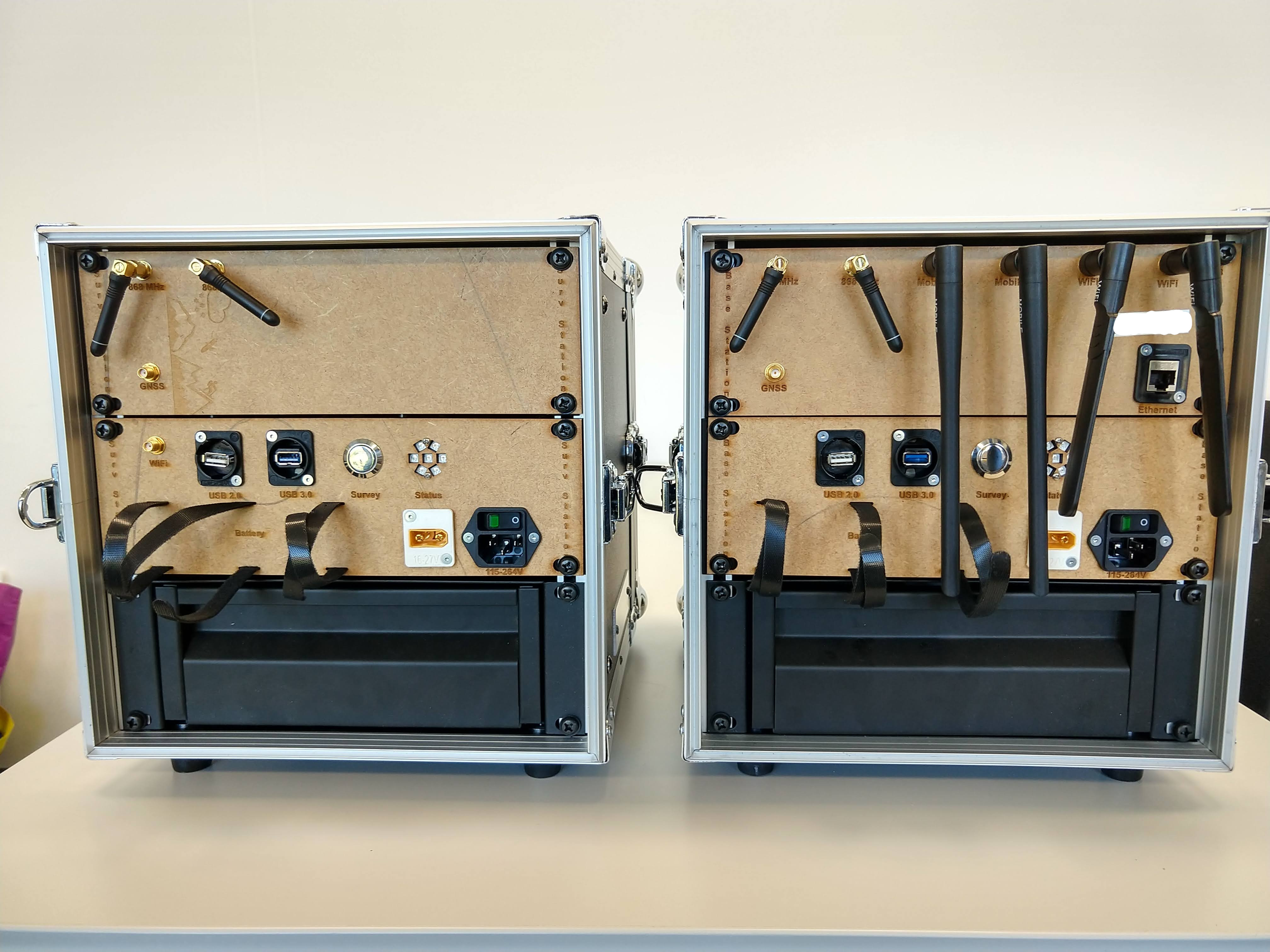
## Base Station
Additionally, the base station spans a 2.4 and 5 GHz WiFi network and exposes
- WiFi and mobile internet antennas
- ethernet port
<img src="https://user-images.githubusercontent.com/11293852/84021399-cc80ed00-a984-11ea-9ab7-7fb420d9b92a.jpg" alt="Base station front" width="480"/>
Its internals contain from left to right
- BOB-11189 RS232<->UART transceiver
- DELL Gateway 3001 (Ubuntu Server 18.04, 32GB recommended) (24V)
- Arduino Micro (12V)
- Adafruit 757 PPS logic level translator
- PV1F240SS survey button (5V)
- Neopixel Jewel status LED (5V)
- 5V, 12V, 24V power distribution board
- PLA50F-24 power supply
- [RFD 868x Modem](https://github.com/ethz-asl/ethz_piksi_ros/wiki/RFD-868x-Modem) on RFD900 to RS232 Interface board
- Piksi DURO (12V)
- RUTX11 mobile router (24V)
<img src="https://user-images.githubusercontent.com/11293852/84021373-c12dc180-a984-11ea-8692-61ff5744580b.jpg" alt="Survey station internal" width="680"/>
## Survey Station
The survey station does not have a router and is connected to the base station network through WiFi.
<img src="https://user-images.githubusercontent.com/11293852/84021387-c854cf80-a984-11ea-898c-2a290b8ce182.jpg" alt="Survey station front" width="480"/>
Its internals contain from left to right
- 4dBi WRT004ANT
- BOB-11189 RS232<->UART transceiver
- DELL Gateway 3001 (Ubuntu Server 18.04, 32GB recommended) (24V)
- Arduino Micro (12V)
- PV1F240SS survey button (5V)
- Adafruit 757 PPS logic level translator
- Neopixel Jewel status LED (5V)
- 5V, 12V, 24V power distribution board
- PLA50F-24 power supply
- [RFD 868x Modem](https://github.com/ethz-asl/ethz_piksi_ros/wiki/RFD-868x-Modem) on RFD900 to RS232 Interface board
- Piksi DURO (12V)
<img src="https://user-images.githubusercontent.com/11293852/84021383-c68b0c00-a984-11ea-941b-1c00c962b914.jpg" alt="Survey station internal" width="680"/>
The survey antenna is mounted on a
- Leica GLS12 2m pole
- Leica GAD105 adapter
<img src="https://user-images.githubusercontent.com/11293852/84022035-f1c22b00-a985-11ea-8d98-b293cc7628df.jpg" alt="Survey pole" width="680"/>
## Connectivity
All devices, except the 868MHz modem, are directly powered through the power board.
The 868MHz modem is powered through the 8 pin Piksi DURO serial connector.
The Piksi DURO connects through ethernet to the router and through UART0 to the 868MHz modem. Optionally, the AUX connector connects the PPS signal through 757 to pin 2 GPIO of the DELL gateway and the UART1 NMEA timing signal to the second RS232 port.
The Arduino Micro pin 6 connects to the Neopixel data input.
Its serial connection is connected to the Dell's first RS232 port via BOB-11189.
The PV1F240SS push button connect 5V to Dell's pin 1 GPIO.
# Installation
The system requires [piksi_multi_cpp](https://github.com/ethz-asl/ethz_piksi_ros/tree/master/piksi_multi_cpp) and its [autostart](https://github.com/ethz-asl/ethz_piksi_ros/blob/master/piksi_multi_cpp/install/install_autostart.sh) feature.
The [interface installation script](https://github.com/ethz-asl/ethz_piksi_ros/blob/master/piksi_multi_interface/install/install.sh) describes the setup procedure.
The [interface installation script](https://github.com/ethz-asl/ethz_piksi_ros/blob/master/firmware/setup.sh) installs the Arduino firmware via command line.
Optionally, [PPS sync installation script](https://github.com/ethz-asl/ethz_piksi_ros/blob/master/piksi_pps_sync/install/install.sh) will setup chrony to synchronize the system clock with GNSS time.
# Acknowledgement
The development of this robotic base station was kindly supported by [Project FindMine](https://www.ue-stiftung.org/findmine) and the Urs Endress Foundation.
 RTK ROS驱动程序,Python (262个子文件)
  pps-gpio-poll.c 5KB pps-gpio-modprobe.c 3KB position_sampler.cc 11KB settings_io.cc 10KB ros_receiver_state.cc 6KB receiver_base_station.cc 5KB ros_time_handler.cc 4KB receiver_factory.cc 4KB device_usb.cc 4KB geotf_handler.cc 4KB ros_relays.cc 4KB ros_conversion.cc 4KB device_serial.cc 4KB udp_observation_sender.cc 4KB sbp_callback_handler_factory.cc 3KB device_tcp.cc 3KB ros_imu_relay.cc 3KB ros_enu_relays.cc 3KB pushbutton_node.cc 3KB device_factory.cc 3KB cb_to_raw_obs_converter.cc 2KB piksi_multi_config_node.cc 2KB udp_observation_receiver.cc 2KB receiver_ros.cc 2KB receiver.cc 2KB ros_mag_relay.cc 2KB piksi_multi_node.cc 1KB device.cc 1KB sbp_callback_handler.cc 1KB receiver_position.cc 910B sbp_observation_callback_handler.cc 899B file_observation_logger.cc 891B receiver_attitude.cc 276B .clang-format 74B .clang-format 74B .clang-format 74B CODEOWNERS 345B kinematic.conf 4KB single.conf 4KB GpsRtkPlugin.cpp 22KB SBPDecoder.cpp 5KB ros-conversion-test.cpp 4KB SBPStreamDecoder.cpp 3KB evaluate_pps 767B example 141B generator 3KB geodetic_survey 139B .gitignore 2KB .gitignore 320B .gitignore 18B ros_relays.h 6KB ros_enu_relays.h 5KB ros_conversion.h 5KB ros_receiver_state.h 3KB settings_io.h 3KB receiver_factory.h 3KB sbp_callback_handler_relay.h 3KB cb_to_raw_obs_converter.h 3KB position_sampler.h 3KB sbp_observation_callback_handler.h 3KB sbp_lambda_callback_handler.h 2KB geotf_handler.h 2KB ros_relay.h 2KB ros_time_handler.h 2KB ros_ext_event_relay.h 2KB receiver_ros.h 2KB udp_observation_sender.h 1KB device.h 1KB sbp_callback_handler.h 1KB udp_observation_receiver.h 1KB sbp_callback_handler_factory.h 1KB sbp_additional_msgs.h 1KB sbp_relay.h 1KB ros_imu_relay.h 1KB receiver_base_station.h 1KB receiver.h 1KB ros_mag_relay.h 1KB device_factory.h 1015B device_tcp.h 991B callback_observation_interface.h 889B file_observation_logger.h 860B receiver_position.h 844B device_usb.h 766B device_serial.h 764B raw_observation_interface.h 673B device_dummy.h 662B receiver_attitude.h 648B SBPDecoder.hpp 7KB GpsRtkPluginThreads.hpp 5KB GpsRtkPlugin.hpp 4KB SBPStreamDecoder.hpp 2KB config_base_2_3_19.ini 5KB config_ref_2_3_19.ini 5KB config_att_2_3_19.ini 5KB config_base_2_3_19.ini 5KB config_rover_2_3_19.ini 5KB config_ref_2_3_19.ini 5KB config_att_2_3_19.ini 5KB rsl_base_station_firmware_1-5-12.ini 5KB rsl_rover_firmware_1-5-12.ini 5KB
共 262 条
- 1
- 2
- 3
资源评论


埋在地下的土豆
- 粉丝: 0
- 资源: 17


最新资源
- 基于Kotlin语言的Android开发工具类集合源码
- 零延迟 DirectX 11 扩展实用程序.zip
- 基于Java的语音识别系统设计源码
- 基于Java和HTML的yang_home766个人主页设计源码
- 基于Java与前端技术的全国实时疫情信息网站设计源码
- 基于鸿蒙系统的HarmonyHttpClient设计源码,纯Java实现类似OkHttp的HttpNet框架与优雅的Retrofit注解解析
- 基于HTML和JavaScript的廖振宇图书馆前端设计源码
- 基于Java的Android开发工具集合源码
- 通过 DirectX 12 Hook (kiero) 实现通用 ImGui.zip
- 基于Java开发的YY网盘个人网盘设计源码
资源上传下载、课程学习等过程中有任何疑问或建议,欢迎提出宝贵意见哦~我们会及时处理!
点击此处反馈


