RMII转MII VHDL 文件代码PDF
需积分: 9 195 浏览量
2022-05-19
23:08:14
上传
评论
收藏 1.18MB PDF 举报

Reduced MII - MII Adapter- T. R. Arun Dec 18’97
National Semiconductor Confidential
page 1 of 21
Reduced MII
This document describes the implementation details of a RMII to MII Adapter.
Description:
The module translates RMII to MII on the receive side and translates MII to RMII on the transmit
side. The goal of this design is a). to support internal MII as well as an external MII and b). to
have a single clock domain. The internal MII refers to design where the translator design would
reside within a MAC like device while the external MII refers to an exposed MII like device. This
module also supports a mode in which the RMII mode can be bypassed individually for receive
and transmit.
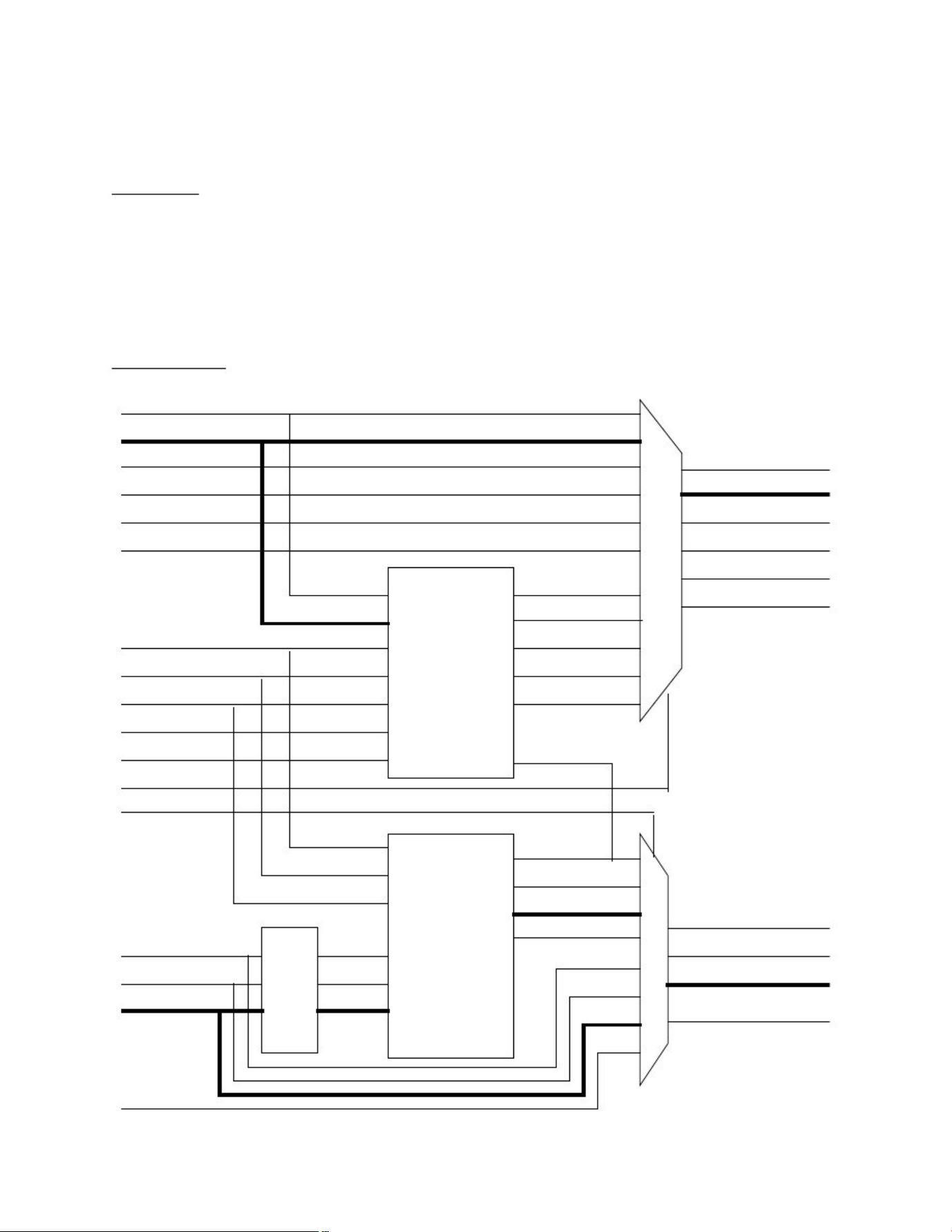
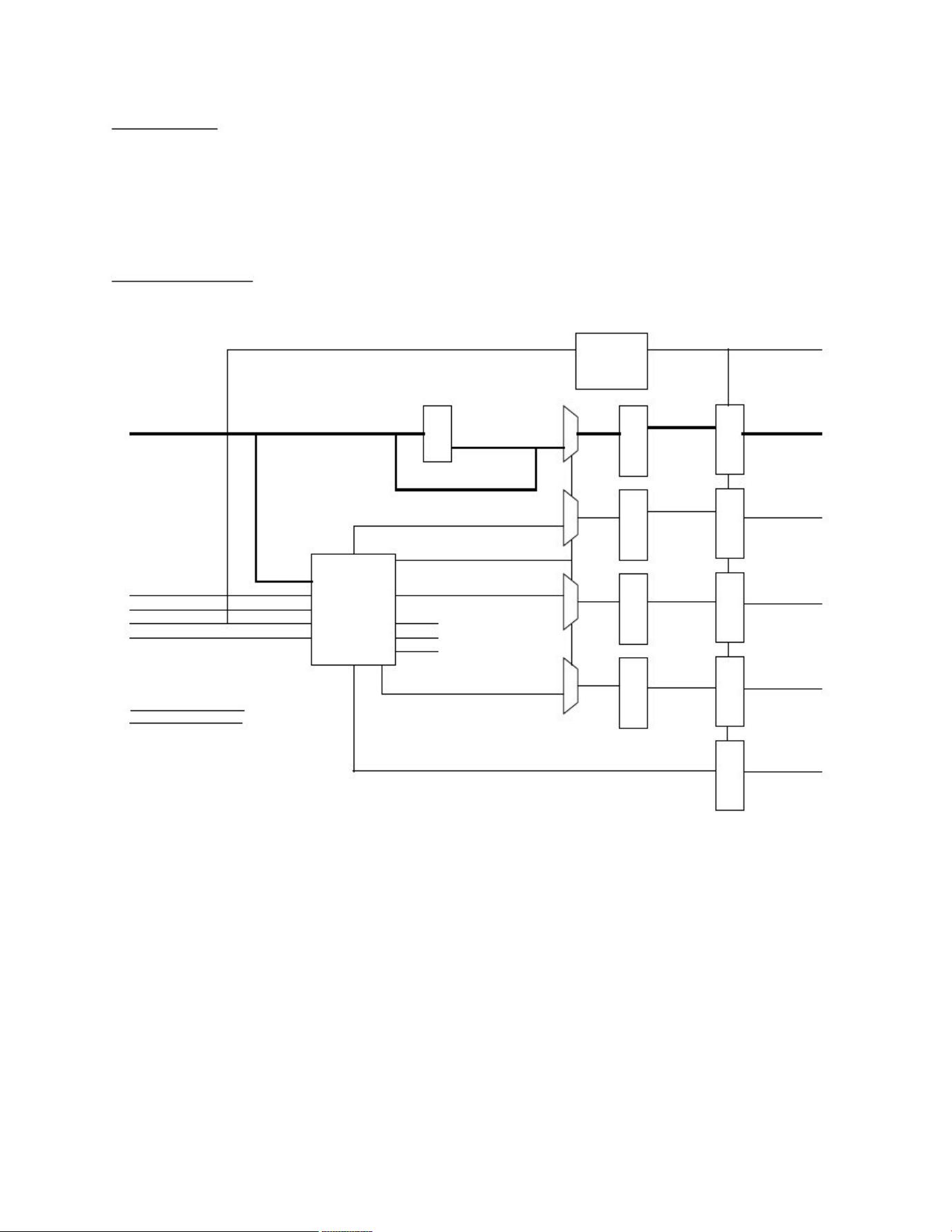
Block Diagram:
crs_in
rxclk_in
rxd_in[3:0]
rxdv_in
rxer_in
col_in
rmii_crs
rmii_rxd[3:0]
rmii_rxdv
rmii_rxer
rmii_col
clk_50m
reset
speed_10
sel_rmiirx
f_duplex
async_mode
PDX_RX
crs_out
rxd_out[3:0]
rxclk_out
rxdv_out
rxer_out
col_out
txen_in
txer_in
R
E
T
I
M
E
rt_txen
rt_txer
rmii_txen
txen_out
txd_out[3:0]
txer_out
rmii_txer
rmii_txd[3:0]
txd_in[3:0] rt_txd
sel_rmiitx
PDX_TX rmii_txclk
txclk_out
txclk_in

剩余20页未读,继续阅读
资源评论


