


zp
zpzp
zp {
{{
{
iGpGv
iGpGviGpGv
iGpGv
Trace with Via; Ground Plane with Apertures

2
Ansoft SIwave v1.1
laG
laGlaG
laG{GG}bGnGwGGh
{GG}bGn Gw GG h {GG}bGn Gw GG h
{GG}bGn Gw GG h
Trace with Via; Ground Plane with Apertures
The objective of this exercise is to become familiar with more features in SIwave
such as traces, vias and apertures. The structure to be analyzed in this exercise has
been chosen because it shows a good overview of SIwave features. We assume
that you have done the SIwave Getting Started exercise in which a rectangular
board structure without signal traces is analyzed.
The following illustration details the PCB you will be creating to determine the
effects of plane apertures and vias.

3
Ansoft SIwave v1.1
u
uu
u
Notice:
The information contained in this document is subject to change without notice.
Ansoft makes no warranty of any kind with regards to this material, including, but not
limited to, the implied warranties of merchantability and fitness for a particular
purpose. Ansoft shall not be liable for errors contained herein or for incidental or
consequential damages in connections with the furnishing, performance, or use of
this material.
This document contains proprietary information which is protected by copyright. All
rights are reserved.
Ansoft Corporation
Four Station Square
Suite 200
Pittsburgh, PA 15219
(412) 261-3200
Unix® is a registered trademark of UNIX System Laboratories, Inc.
Windows™ is a trademark of Microsoft® Corporation.
© 1984—2003 Ansoft Corporation
4
Ansoft SIwave v1.1
laGnGz
laGnGzlaGnGz
laGnGz
Launching SIwave
Start Maxwell Control Panel
Click on the Project button
Create and open a New SIwave v1
Project named: apertures
Creating the Model
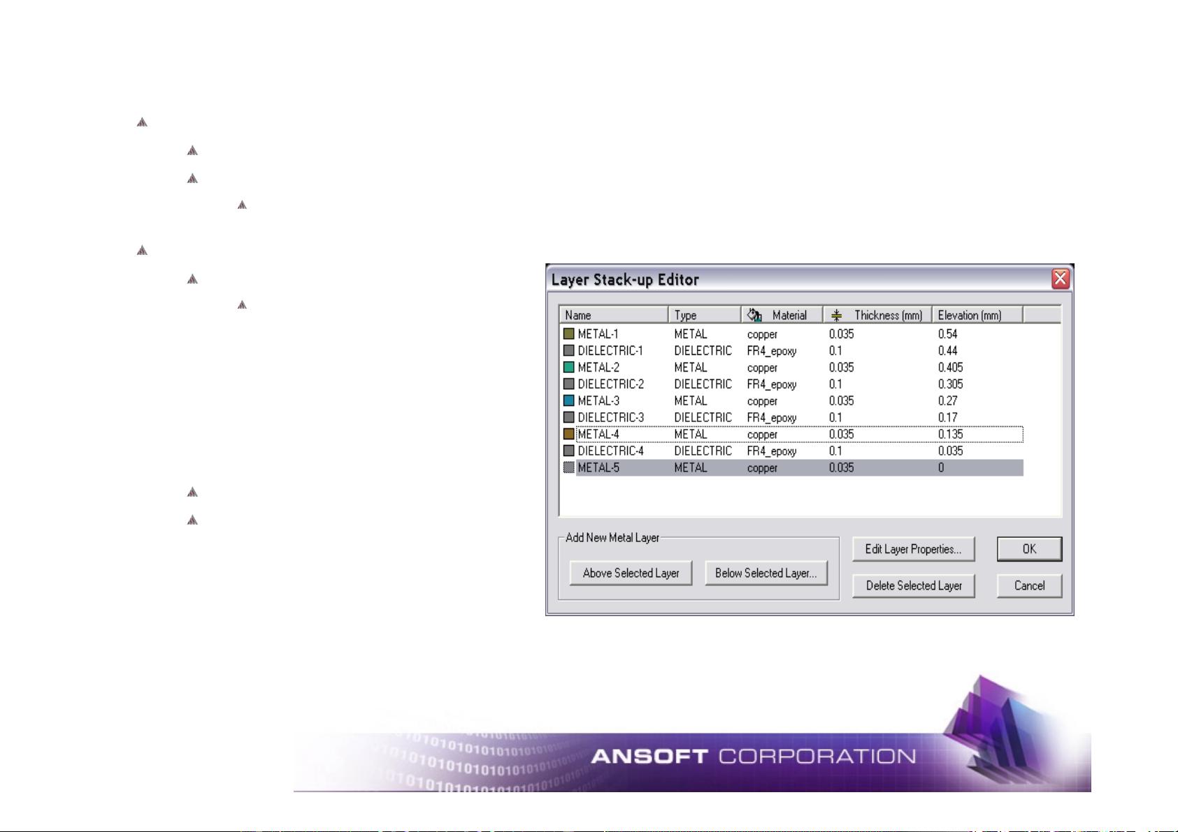
Select Edit/Layer Stack
There are four metal layers and
three dielectric layers defined by
default. In this exercise, we want
five metal layers and four dielectric
layers. Metal layers 1, 3, and 5 will
be power and ground planes while
metal layers 2 and 4 will be signal
layers. Hence, we need to add one
metal layer and one dielectric layer.
Click on Metal-4 to select it
Click Add New Metal Layer /
Below Selected Layer.
Immediately, a dielectric and a metal
layer, with default materials and
thicknesses, are added to the bottom of
the stack. The existing layers are
elevated automatically so the stack still
starts at elevation zero.

5
Ansoft SIwave v1.1
laGsG
laGsGlaGsG
laGsGz
zz
z
Select the layers one by one by clicking on them and select Edit Layer Properties (or
double-clicking on them)
In the Layer Properties window that comes up for each layer, change colors to
brighter colors as you see fit. Also, you can change names of layers as you see fit,
for instance, you can change the names of the metal layers, from 1 to 5, to power,
signal_top, ground_center, signal_bottom, ground, respectively. Do not change the
elevation or thickness of any layer – we accept the defaults for this exercise.
Click OK when finished
Blue
Sample
Colors
Red
Blue
Red
Blue


