没有合适的资源?快使用搜索试试~ 我知道了~
安川505W2系列变频器英文说明书.doc
1.该资源内容由用户上传,如若侵权请联系客服进行举报
2.虚拟产品一经售出概不退款(资源遇到问题,请及时私信上传者)
版权申诉
0 下载量 85 浏览量
2023-08-29
22:57:12
上传
评论
收藏 828KB DOC 举报
温馨提示
试读
20页
安川505W2系列变频器英文说明书.doc
资源推荐
资源详情
资源评论
Varispeed -505WII
INDUSTRIAL USE THYRISTOR CONVERTER UNITS
Before initial operation, read these instructions thoroughly, and retain for future reference.
YASKAWA
When properly installed, operated and maintained, this
unit will provide a lifetime of optimum operation. It is
mandatory that the person who operates, inspects, and
maintains this equipment thoroughly reads and understands
this manual and has In his possession at all time.
IMPORTANT
• Make no withstand voltage test on the VS-505WII because
it Incorporates semi-conductor electronic circuits.
• If insulation resistance tests are neccessary, make them
only In accordance with the Instructions given in this
manual.
• Do not tamper with potentiometers of the power units
since they were preset at the factory before shipment.
Varispeed-505WII (VS-505WII) is a thyristor converter unit
for varispeed reversible operation of industrial DC
motors.
For correct operation of VS-505WII, users must
thoroughly read these instructions. This manual is also
necessary for maintenance and troubleshooting, and
threfore should be kept filed for ready reference.
For details on DC motors, refer to "Instructions for
Industrial DC Motors" CTOE-C435-3B).
Type CDMR-WH (Type
S)
460 V,105 A
Type CDMR-WI (Type
L)
460 V, 420 A
682-227
Type CDMR-WI (Type
M) 230 V, 260 A
RECEIVING .................................. 3
STORAGE...................................... 3
LOCATION.................................... 3
INSTALLATION........................... 3
WIRING.......................................... 3
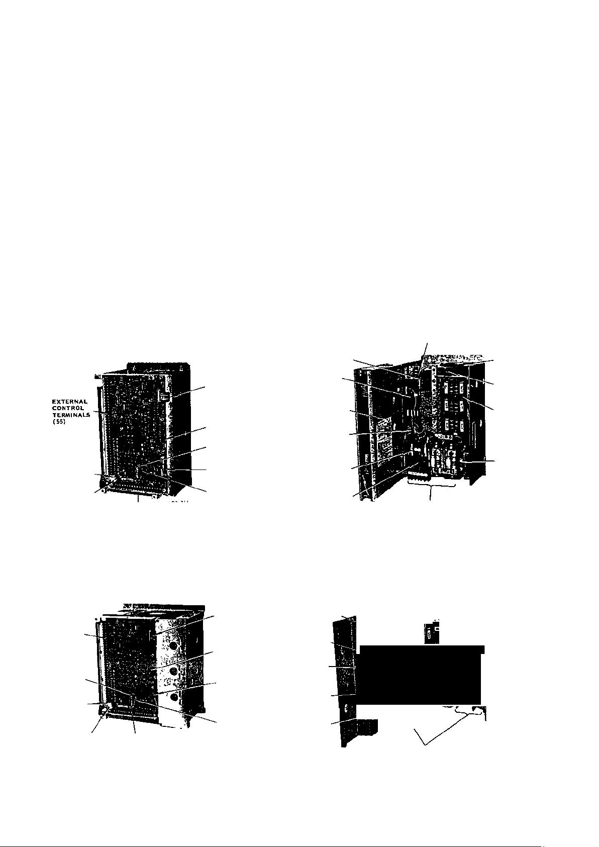
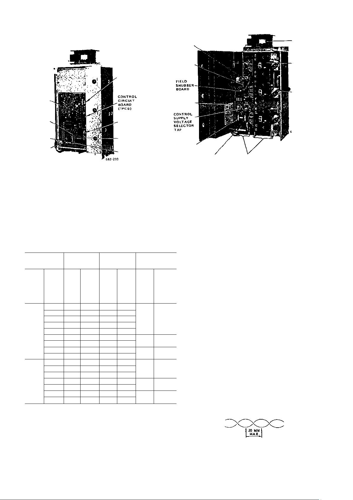
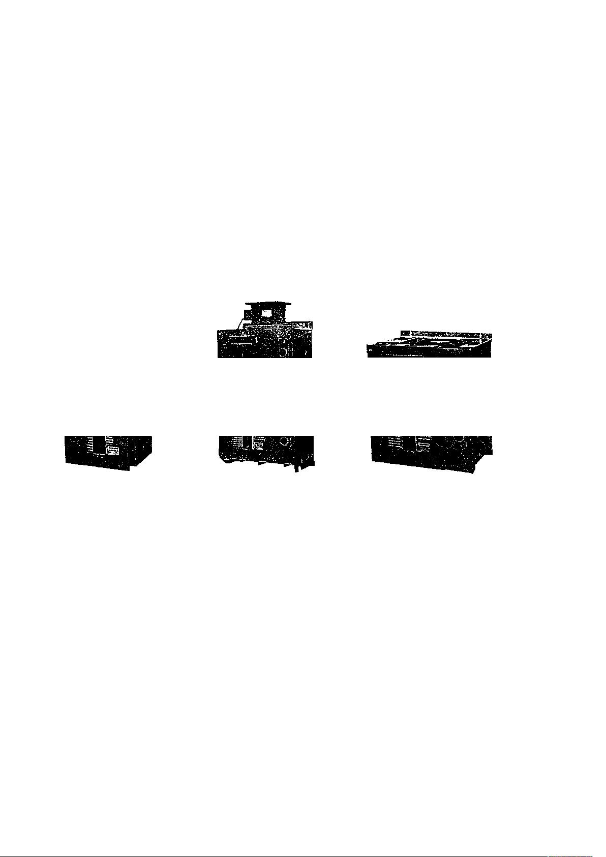
Component Arrangement in VS-
505WII............................................. 3
Terminal Sizes and Carrying
Currents.............................................4
CONTENTS
Interconnections................................4
Cautions when Wiring .....................4
TEST RUN...................................... 5
Check before Test
Run.................................................... 5
No-Load Operation ..........................6
Full-Load Operation.........................6
Adjustment....................................... 6
MAINTENANCE...................... 10
Periodic Inspection ..................... 10
Parts Replacement ...................... 10
Cautions in Replacing
Control Board.............................. 14
Troubleshooting Guide . … 1 4
SPARE PARTS.......................... 15
REFERENCE.................................16
2
POWER CIRCUIT
BOARD (2PCB)
CONNECTOR
CONTROL CIRCUIT
BOARD (1PCB)
EXTERNAL
CONTROL
TERMINALS
(55)
OPERATION
INDICAT
丨
NC LIGHT
FUSE BLOWN
DETECTION
CONNECTOR
DETECTION
CONNECTOR
CONNECTOR
OCL RESET
INDICATING
LICHTS (6)
RECEIVING
The equipment has been put through severe tests at the
factory before shipped. After unpacking
9
however, check
and see the following
• Its nameplate data meets your requirements.
• It has sustained no damage while in transit.
• Fastening bolts and screws are not loosened.
• Devices built in the cabinet are not damaged or
missing.
STORAGE
If the equipment is temporarily stored or machine stops
for an extended length of time, the following precautions
should be taken.
LOCATION
Store the equipment under the following conditions.
• Free from rainfall and drops of water
• Clean and dry
FU SE BL OW N
DETECTION
CONNECTOR
CURRENT
DETECTION
CONNECTOR
FAILURE
INDICATING
LICHTS (6)
POWER CIRCU IT
BOARD (2PCB)
CONNECTOR
CONTROL CIRCUIT
BOARD (1PCB)
OPERATION
INDICATINC
LIGHT
CONTROL
POWER
CONNECTOR
OCL RESET
PUSHBUTTON
(a) Control Circuit
Fig. 1 Type CD
• Free from corrosive gas and liquid
• Ambient temperature: 0°C to 40°C
• Less vibration
INSTALLATION
Select a location described in STORAGE and install the
equipment by proper procedure in keeping the equipment in
good working condition.
WIRING
Make wiring in reference to the interconnection diagram
furnished on your order and the following.
COMPONENT ARRANGEMENT IN
VS-505WH
Figs. 1 to 3 show component arrangement in the VS-
505WE.
POWER CIRCUIT
BOARD (2PCB)
CONTROL CIRCUIT
BOARD "PCBl
CONNECTOR
NAMEPL
ATE
"CAUTIO
NS
IN
OPERA-
TION"
CONTROL
SUPPLY
VOLTACK
SELECTO
R
TAP
SURGE
ABSORBE
RS
FUSES (?)
SURGE
ABSOR
BEERS (3)
THYRISTOR
COOLING FAN
MAIN CIRCUIT
EXTERNAL
TERMI NAL
SNUBBER BOARDS
(4PCB)
THYRISTOR
PROTECTIV
E
FUSE
(2 FOR
220 V
CLASS, 3 FOR
440 V CLASS)
682-217
MAIN CIRCUIT
EXTERNAL
TERMINALS
(b) Main Circuit
MR—Wit, -S (460 V, 115 A)
ILFJ ⑵ ^
LDBCBEP3UP
T
E
N;
R
PLTAECGEORESCEOR
SER&amcanioonupolelap
郎
5BS3)
F B ( N l l r T C S V S T
s A F s A (
CONTROL CIRCUIT
BOARD (1PCB) THYRI STOR
CONNECTOR POWER CIRCU IT COOL ING
y BOARD (2PCB) FAN
\
flBnSBEBEEKMfiBVRf
lS
B
Uil h
;
^ j,,pi
SNUBBER
.BOARD
(UPCB)
THYRISTOR
PROTECTIVE
FUSE
(2 FOR 220
V CLASS, 3
FOR U40 V
CLASS)
MAIN CIRCUIT
EXTERNAL
TERMI NAL
(a) Control Circuit (b) Main Circuit
Fig. 2 Type CDMR-WE, -M (230 V, 260 A)
3
WIRING (Cont'd)
POWER CIRCU IT
BOARD (2PCB)
CONNECTOR
EXTERNAL
CONTROL
TERMINALS
(55)
OPERATION
INDICATING
LIGHT
FUSE BLOWN
DETECTION
CONNECTOR
CURRENT
DETECTION
CONNECTOR
POWER CIKCUI
BOARD (2PCB)
CONTROL CIRCUIT
BOARD (1PCB)
CONNECTOR
R c _
o ^ -
N t ?
OLCTSEUTEpt
TRERNEC
ONOWONCLUSO
NAILICH
C P C
O P T F l h L
THYRISTOR
COOLINC
FAN
NAMEPLATE
"CAUTIONS
IN OPERA-
THYRISTOR
PROTECTIVE
FUSE
(2 FOR 220 V
CLASS, 3 FOR
440 V CLASS)
R
)
E
2
B
CEOR
is
URBSUS
s A
F
SURGE
ABSORBERS
(3)
MAIN CIRCUIT EXTERNAL
TERMINALS
(a)
Control Circuit (b) Power Circuit
Fig. 3 Type CDMR-WE, -L (460 V, 420 A)
TERMINAL SIZES AND CARRYING CURRENTS INTERCONNECTIONS
Table 1 shows the size and the current earring capacities
of the terminals of VS-505WII. Select leads with
sufficient current carrying capacity. Refer to "Cautions
when Wiring".
Table 1 Terminal Size and Current Capacity
CDMR-WI
AC Main
Circuit
DC Main
Circuit
Field
Circuit
Rated
Volt
age
V
Rated
Out
put
kW
Ter
minal
Size
Car
rying
Cur
rent
A
Ter
minal
Size
Car
rying
Cur
rent
A
Ter
minal
Size
Car
rying
Cur
rent
A
25
M4
21
M5
25
35
M8
29
M8
35
45
M8
37
M8
45
90
M8
74
M8
90
105
M8
86
M8
105
M4
12
180
M10
147
M10
180
260
M10
213
M10
260
M4
22
420
M12
343
M12
420
230
550
M12
449
M12
.550
M4
25
50
M8
41
M8
50
90
M8
74
M8
90
105
M8
86
M8
105
M4
12
180
M10
147
M10
180
260
M10
213
M10
260
M4
22
420
M12
343
M12
420
M4
460
550
M12
449
M12
550
25
Notes :
■ Terminal size other than listed above is M4 and current
capacity is 2 A or below.
• Rule of thumb of AC main circuit power capacity 1.2 x/3
x e X I (VA)
E : Supply voltage I : AC main
circuit current
Make connections of VS-505WI with associate units
according to the interconnection diagram separately
furnished.
CAUTIONS WHEN WIRING
Main Circuits
Use 600 V PVC insulated wires or cabtyre cables with the
current carrying capacities of the combined DC motor for AC
main circuit terminals (U, V
,
W) and DC main circuit
terminals (P, N).
Field Circuits
Use 600 V PVC insulated wires or cabtyre cables with the
current carrying capacities of the combined DC motor for
field power circuit terminals (Uo, Wo» Ui, Wi) and field
circuit terminals (J, K). Use stranded wires of cross-
section 5.5 mm
2
or larger for field circuit terminals (J,
K).
Signal Circuits
Use shielded wires or twisted wires of twisting pitches 20
mm or smaller for the speed setting circuit terminals (6 to
10
),
speed feedback terminals (2, 3), tachometer circuit
terminals (50 to 52).
Fig. 4 Pitch of Twisted Wire
4
剩余19页未读,继续阅读
资源评论
oligaga
- 粉丝: 52
- 资源: 2万+
上传资源 快速赚钱
- 我的内容管理 展开
- 我的资源 快来上传第一个资源
- 我的收益 登录查看自己的收益
- 我的积分 登录查看自己的积分
- 我的C币 登录后查看C币余额
- 我的收藏
- 我的下载
- 下载帮助
安全验证
文档复制为VIP权益,开通VIP直接复制
信息提交成功