没有合适的资源?快使用搜索试试~ 我知道了~
安捷伦示波器探头 Selection Guide
需积分: 5 1 下载量 201 浏览量
2022-05-09
20:15:26
上传
评论
收藏 1.37MB PDF 举报
温馨提示
试读
18页
安捷伦示波器探头 Selection Guide
资源详情
资源评论
资源推荐
To get the most out of your oscilloscope, you need the right
probes and accessories for your particular applications. Whether
you need the high bandwidth and low loading of an active probe,
an easy way to connect to surface mount ICs or a passive probe
to measure high voltages, there’s a wide selection of high-quality
probes and accessories for your Agilent oscilloscope.
Agilent Oscilloscope Probes
and Accessories
Selection Guide
2
How to select a probe
Selecting the correct probe for your
oscilloscope measurement should not
be difficult. This brochure provides
suggestions on how to make the best
decision. Following is a list of probe
parameters you need to consider
when you select a probe for a given
measurement.
Attenuation
Choose the attenuation ratio of the
probe (1:1, 10:1, 100:1, 1000:1) to
match the test signal amplitude to
the oscilloscope’s vertical sensitivity
range.
Bandwidth (BW)
The probe’s rated bandwidth should
match the oscilloscope and be
adequate for the test signal. However,
at higher frequencies, grounded lead
inductance and input capacitance
often influence system performance
more than probe bandwidth does.
Input resistance (Rin)
Input impedance is used to describe
the loading effects of a probe. At DC
and low frequency ranges, the probe’s
resistive component is the main factor
that loads down the circuit under test.
However, as the frequency goes up,
the capacitance of the probe tip in
parallel with the DC resistance starts
to reduce the input impedance of the
probe, resulting in greater loading and
a more adverse effect to the target.
Input capacitance (Cin)
Excessive input capacitance (some-
times called tip capacitance) will slow
down the system’s pulse response.
Usually the least input capacitance
possible is best.
Maximum input voltage (Vmax)
To ensure user safety, help protect the
oscilloscope input from destructive
voltage, and avoid damage to the
probe, select a probe that is rated for
a higher voltage than the signal you
intend to test.
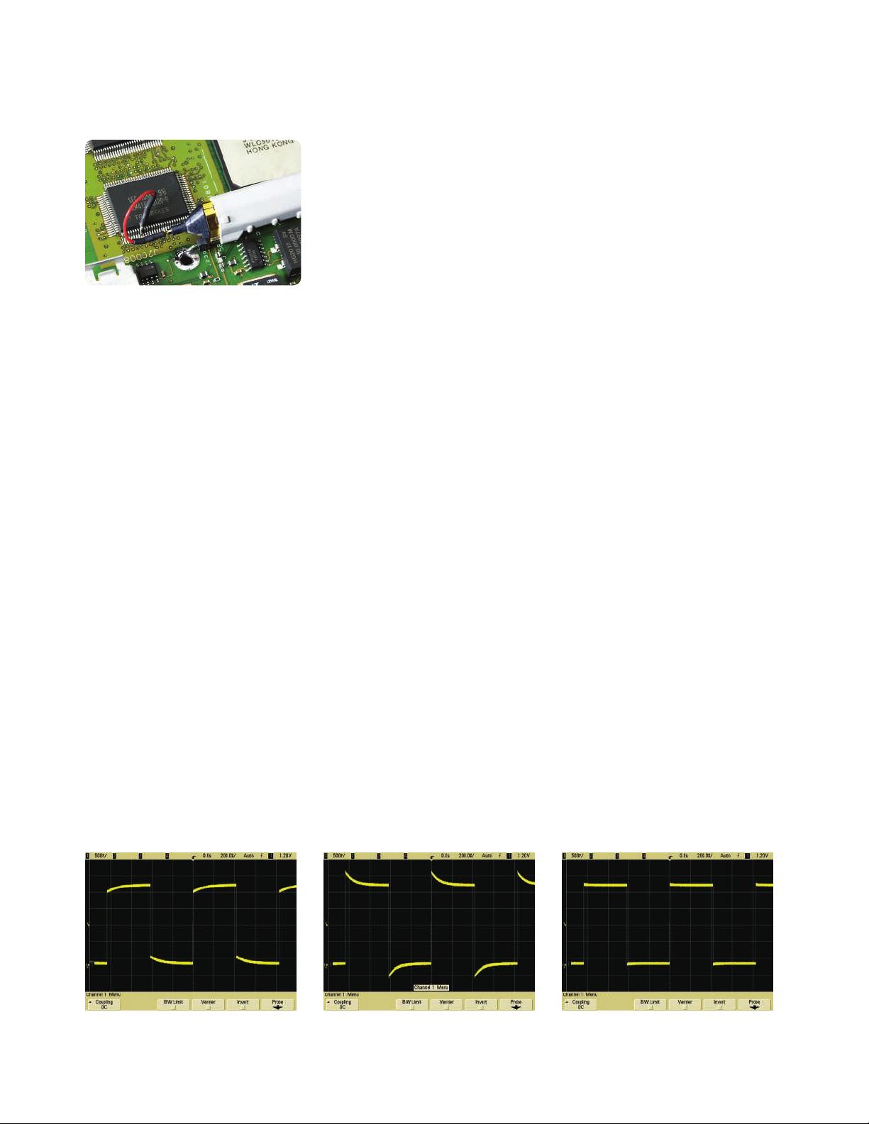
Probe compensation range
Most passive probes have a specifica-
tion that lists the oscilloscope input
capacitance range over which they
can be used. When choosing a passive
probe, be sure that the oscilloscope’s
input capacitance lies within the
probe’s compensation range or you
will not be able to adjust the probe
to achieve a correctly compensated
square wave signal.
Most oscilloscopes have 1-MΩ input
resistance. This input resistance is in
parallel with the input (shunt) capaci-
tance. Normally, high-frequency probes
with attenuation factors greater than
1:1 have adjustable compensation net-
works built into them. Adjusting this
compensation network provides the
best possible frequency linearity over
the oscilloscope’s designed frequency
range. Operating instructions provided
with the probe explain how to adjust
the compensation network to obtain
best signal fidelity.
Probe Interface
Most Agilent oscilloscope probes offer
either BNC type of probe interface
or the AutoProbe interface. The
AutoProbe interface is an intelligent
communication and power link
between compatible probe and the
Infiniium or InfiniiVision Series oscil-
loscopes. The AutoProbe identifies the
type of probe attached and sets up the
proper input impedance, attenuation
ratio, probe power and offset range as
needed.
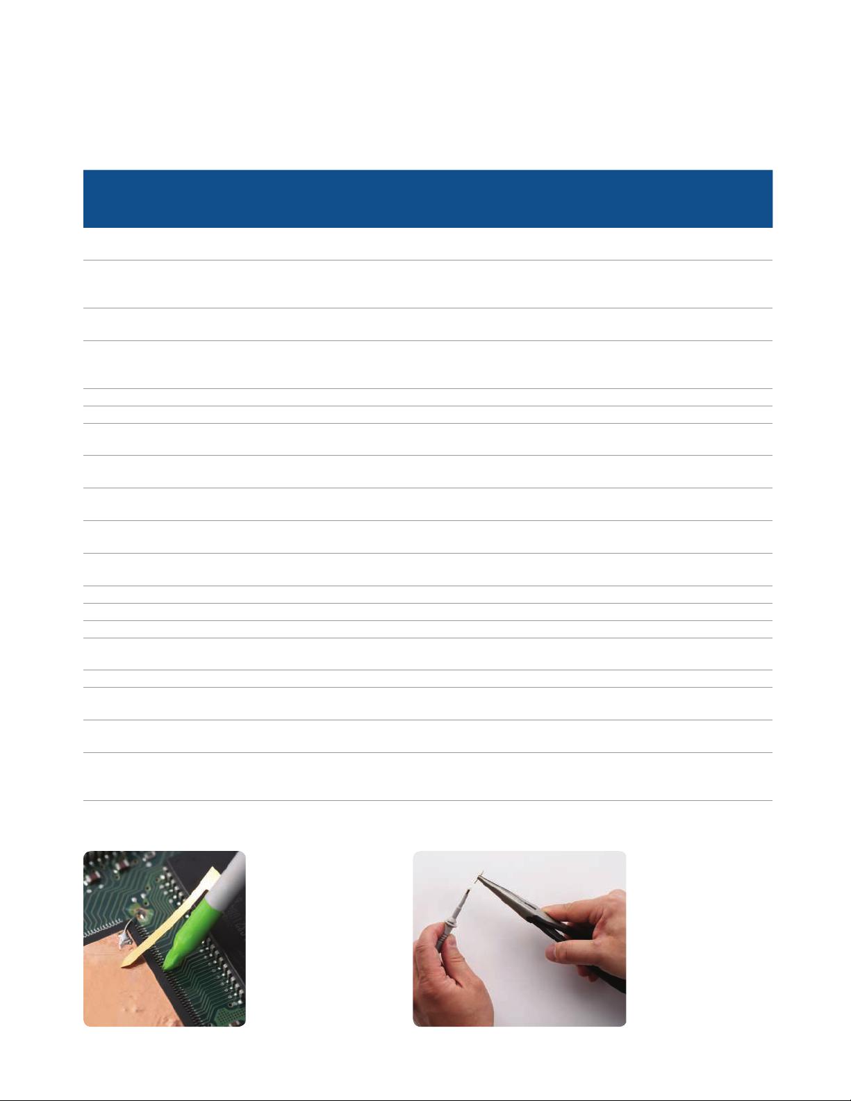
Probe tip form factor
Your probe must make a reliable
connection to the test point, and you
may want it to grab the test point.
Generally, this requires a small and
light probe and a tip or grabber that is
compatible with the test point. SMT
and fine-pitch geometries make this
issue especially critical.
Under-compensated
The effects of passive probe compensation:
Over-compensated Properly compensated
3
Types of probes
Passive probes
The most widely used type of oscil-
loscope probe is the “passive probe.”
Passive probes are also the most
rugged and economical. There are no
active components such as transistors
or amplifiers in the probe, and therefore
passive probes do not need to be
powered.
Passive probes classifications
1:1 high Z
passive probe
10:1 or 20:1 high Z
passive probe
100:1 or 1000:1 high Z
passive probe
Resistive divider
passive probe
Features A low capacitance
coax cable with a BNC
connector on one end
and a probe on the other
• The most widely used
scope probe type;
provided standard
with most < 1-GHz
oscilloscopes
• Gives lower input
capacitance and higher
bandwidth than the 1:1
probe
• Additional attenuation
for use with higher-
amplitude signals
• Large attenuation
requires a high-gain
amplifier on the scope
• Highest-bandwidth
passive probe for
measuring high-
frequency, low-
impedance circuit
• Must be used with an
oscilloscope’s 50-Ω input
When to use For viewing small
signals (< 1 V)
For viewing up to ~300 V For viewing up to
15 kV high voltage
High-frequency,
low-impedance (< 50 Ω)
digital circuit, transmission
line
When not to use For probing high-
frequency signal
For achieving > 700 MHz
system bandwidth
For making floating
(ungrounded)
measurement
For probing high-amplitude,
high-impedance signal
Typical bandwidth Up to 35 MHz Up to 600 MHz Up to 250 MHz Up to 6 GHz
Agilent models N2870A,10070D,
N2889A (1:1/10:1)
N2871/2/3/5A
10073D, 10074D, 1165A,
N2862B/63B/89A/90A,
N2894A
10076B, N2771B N2874/6A, 54006A
4
Passive probe characteristics
Model
Cable
length Attenuation
Typical probe
bandwidth
Compensates
oscilloscope
input
Max input
voltage Recommended oscilloscopes
10070D 1.5 m 1:1 20 MHz 1 MΩ 400 V CAT II 1000, 3000, 2000 X, 3000 X, 4000 X,
5000, 6000, 7000, 8000, 54600 Series
N2870A 1.3 m 1:1 35 MHz 1 MΩ 55 V CAT II 1000, 3000, 2000 X, 3000 X, 4000 X,
5000, 6000, 7000, 8000, 9000 and 54600
Series
N2889A 1.3 m 1:1,10:1 350 MHz 1 MΩ, 5-30 pF 300 V CAT II 1000, 3000, 2000 X, 3000 X, 4000 X,
5000, 6000, 7000, 8000, 9000
10073D 1.5 m 10:1 500 MHz 1 MΩ, 6-15 pF 400 V CAT II 5000 Series (500 MHz) 6000
(300 MHz-1 GHz), 7000, 5464x, 54830
and 8000 Series
10074C 1.5 m 10:1 150 MHz 1 MΩ, 9-17 pF 400 V CAT II 6000 Series (100 MHz), 5462x
N2862B 1.2 m 10:1 150 MHz 1 MΩ, 5-30 pF 300 V CAT II 1000, 3000, 2000 X, 3000 X Series
N2863B 1.2 m 10:1 300 MHz 1 MΩ, 5-30 pF 300 V CAT II 1000, 3000, 2000 X, 3000 X, 5000 Series
(100, 300MHz)
N2871A 1.3 m 10:1 200 MHz 1 MΩ, 10-25 pF 300 V CAT II 1000, 3000, 2000 X, 3000 X, 5000, 6000,
7000, 8000, 9000 and 54600 Series
N2872A 1.3 m 10:1 350 MHz 1 MΩ, 10-25 pF 300V CAT II 1000, 3000, 5000, 6000, 7000, 8000, 9000
and 54600 Series
N2873A 1.3 m 10:1 500 MHz 1 MΩ, 10-25 pF 300V CAT II 1000, 3000, 2000 X, 3000 X, 5000, 6000,
7000, 8000, 9000 and 54600 Series
N2890A 1.3 m 10;1 500 MHz 1 MΩ, 5-30 pF 300 V CAT II 1000, 3000, 2000 X, 3000 X, 5000, 6000,
7000, 8000, 9000
1165A 1.5 m 10:1 600 MHz 1 MΩ, 12-14 pF 300 V CAT II 54830, 6000, 7000, 8000, 9000 Series
N2894A
1
1.3 m 10:1 700 MHz 1 MΩ, 10-25 pF 300 V CAT II 4000 X
N2874A 1.3 m 10:1 1.5 GHz 50 Ω 8.5V CAT I 5000, 6000, 7000 and all Infiniium Series
N2875A 1.3 m 20:1 500 MHz 1 MΩ, 7-20 pF 300V CAT II 1000, 3000, 2000 X, 3000 X, 5000, 6000,
7000, 8000, 9000 and 54600 Series
N2876A 1.3 m 100:1 1.5 GHz 50 Ω 21V CAT I 5000, 6000, 7000 and all Infiniium Series
54006A 1.2 m 10:1 (500 Ω)
or 20:1 (1 kΩ)
6 GHz 50 Ω 20 Vpk 80000, 90000, 5484x, 5485x, 90000X/Q
with N5442A
10076B 1.5 m 100:1 250 MHz 1 MΩ, 7-20 pF 4 kV CAT I
1 kV CAT II
1000, 3000, 2000 X, 3000 X 5000, 6000,
7000, 8000, 9000 Series
N2771B 2 m 1000:1 50 MHz 1 MΩ, 6-20 pF DC: 15 kV
AC: 10 kV
Peak 30 kV
1000, 3000, 2000 X, 3000 X 5000, 6000,
7000, 8000, 9000 Series
Types of probes (continued)
Passive probes
Low-inductive ground
connection for N287xA
probes keeps the probe
loading low to achieve
high signal integrity
measurements
The replaceable probe tip
on the N287xA probes
saves you money
Note [1]: The N2894A provides 700 MHz system bandwidth with the 4000X Series 1 GHz/1.5 GHz models only.
剩余17页未读,继续阅读
Qin_Baba
- 粉丝: 25
- 资源: 27
上传资源 快速赚钱
- 我的内容管理 展开
- 我的资源 快来上传第一个资源
- 我的收益 登录查看自己的收益
- 我的积分 登录查看自己的积分
- 我的C币 登录后查看C币余额
- 我的收藏
- 我的下载
- 下载帮助
安全验证
文档复制为VIP权益,开通VIP直接复制
信息提交成功
评论0