ds18b20资料有英文有中文
需积分: 0 40 浏览量
2010-03-22
20:58:34
上传
评论
收藏 416KB DOC 举报


中英文资料
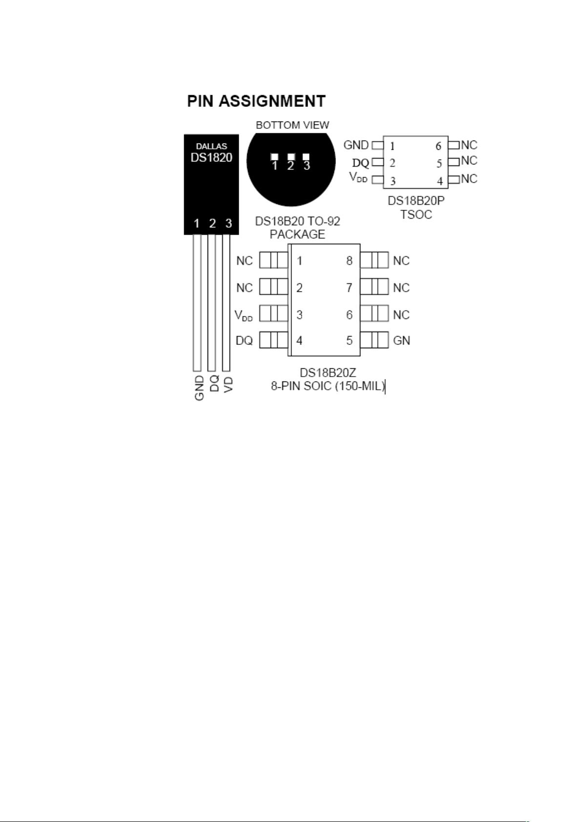
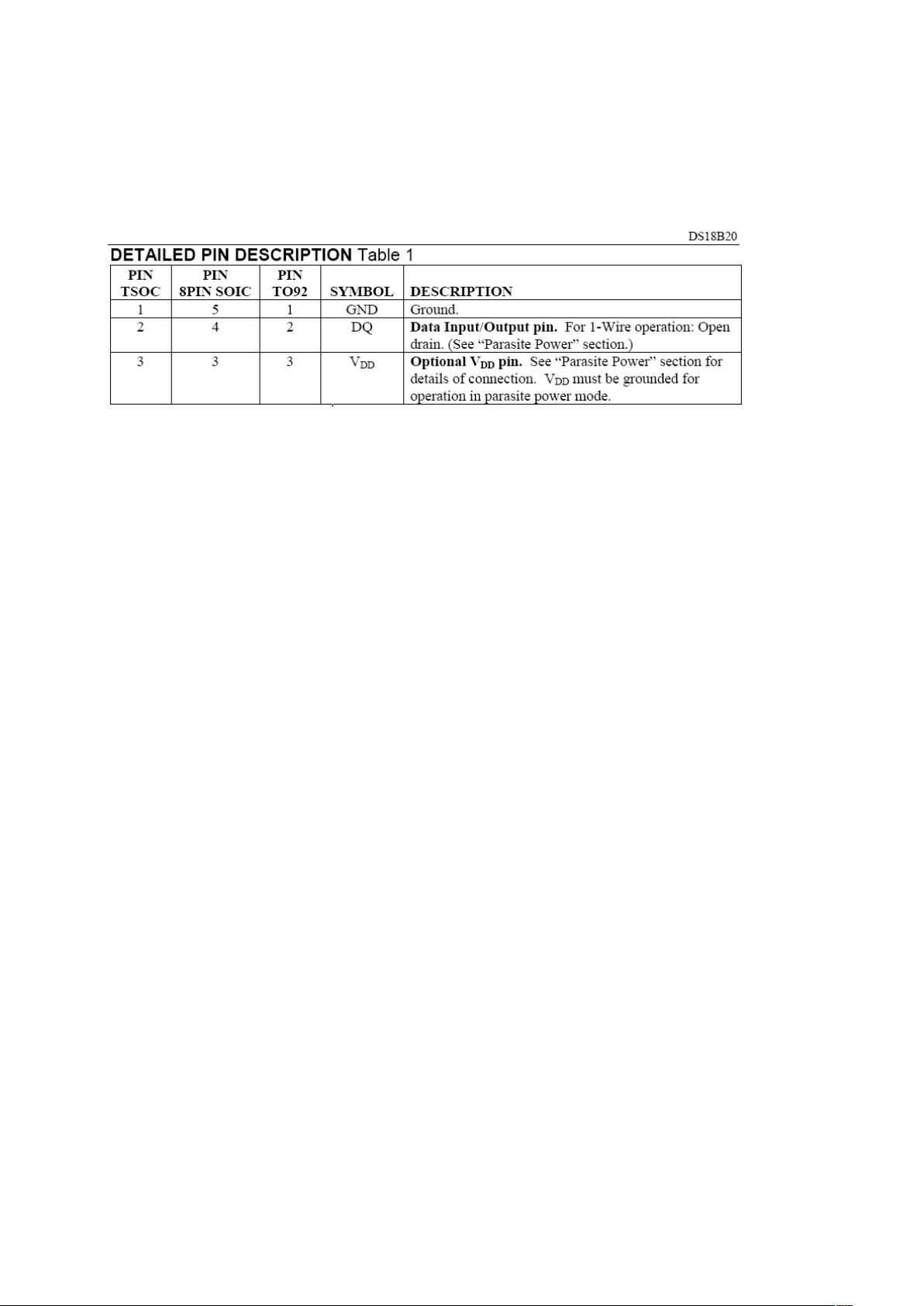
DS18B20
Programmable Resolution
1-Wire Digital Thermometer
FEATURES
_Unique 1-WireTM interface requires only oneport
pin for communication
_.Multidrop capability simplifies distributedtemperature
sensing applications
_ Requires no external components
_ Can be powered from data line. Power supply
range is 3.0V to 5.5V
_ Zero standby power required
_ Measures temperatures from -55°C to
+125°C. Fahrenheit equivalent is -67°F to
+257°F
_ 0.5C accuracy from -10°C to +85°C
_ Thermometer resolution is programmable
from 9 to 12 bits
_ Converts 12-bit temperature to digital word in
750 ms (max.)
_ User-definable, nonvolatile temperature alarm
settings
_ Alarm search command identifies and
addresses devices whose temperature is
outside of programmed limits (temperature
alarm condition)
_ Applications include thermostatic controls,
industrial systems, consumer products,
thermometers, or any thermally sensitive
system


剩余26页未读,继续阅读

lovinguk
- 粉丝: 0
- 资源: 1


最新资源
- 论文(最终)_20240430235101.pdf
- 基于python编写的Keras深度学习框架开发,利用卷积神经网络CNN,快速识别图片并进行分类
- 最全空间计量实证方法(空间杜宾模型和检验以及结果解释文档).txt
- 5uonly.apk
- 蓝桥杯Python组的历年真题
- 2023-04-06-项目笔记 - 第一百十九阶段 - 4.4.2.117全局变量的作用域-117 -2024.04.30
- 2023-04-06-项目笔记 - 第一百十九阶段 - 4.4.2.117全局变量的作用域-117 -2024.04.30
- 前端开发技术实验报告:内含4四实验&实验报告
- Highlight Plus v20.0.1
- 林周瑜-论文.docx
资源上传下载、课程学习等过程中有任何疑问或建议,欢迎提出宝贵意见哦~我们会及时处理!
点击此处反馈


评论0